
Sliding component

a technology of sliding components and components, applied in the direction of engine components, mechanical equipment, coatings, etc., can solve the problems of poor machining properties, high cost, and silicon carbid

Active Publication Date: 2020-06-11
EAGLE INDS +1
View PDF4 Cites 10 Cited by
  • Summary
  • Abstract
  • Description
  • Claims
  • Application Information

AI Technical Summary

Benefits of technology

The present invention formed a smooth sealing face by using an amorphous carbon film with low silicon content, which prevents deposition of silicate compounds from the sealed fluid. This results in a higher dynamic pressure generation mechanism between the sealing faces, leading to a low friction and low leakage state without losing functions of the dynamic pressure generation mechanism. The invention is useful in preventing leakage of various silicate-containing fluids during sealing.

Problems solved by technology

Silicon carbide is a favorable material as the sliding material of the mechanical seal but expensive and poor in a machining property.

Method used


Image

  • Sliding component
  • Sliding component
  • Sliding component

Examples


example 1

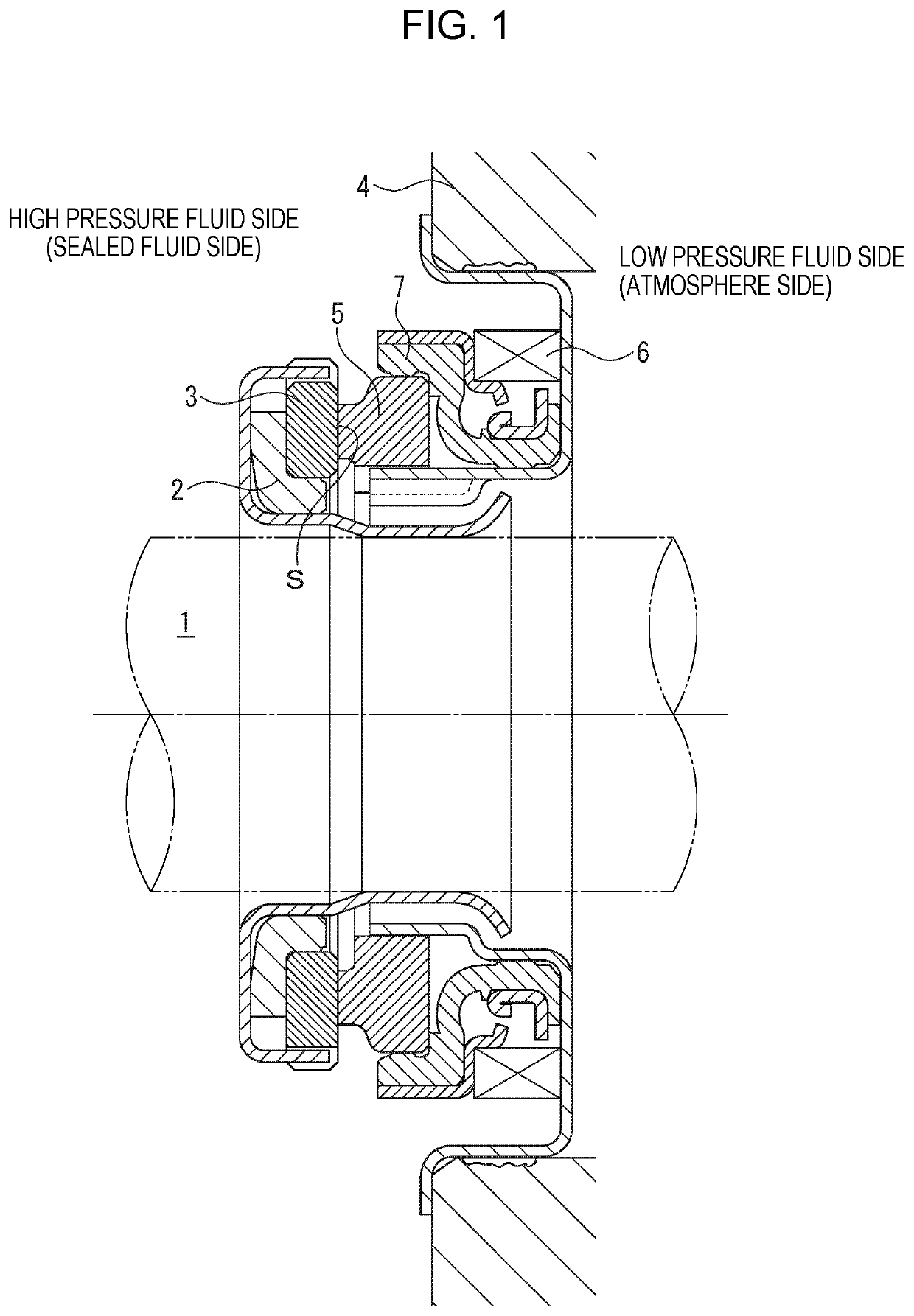
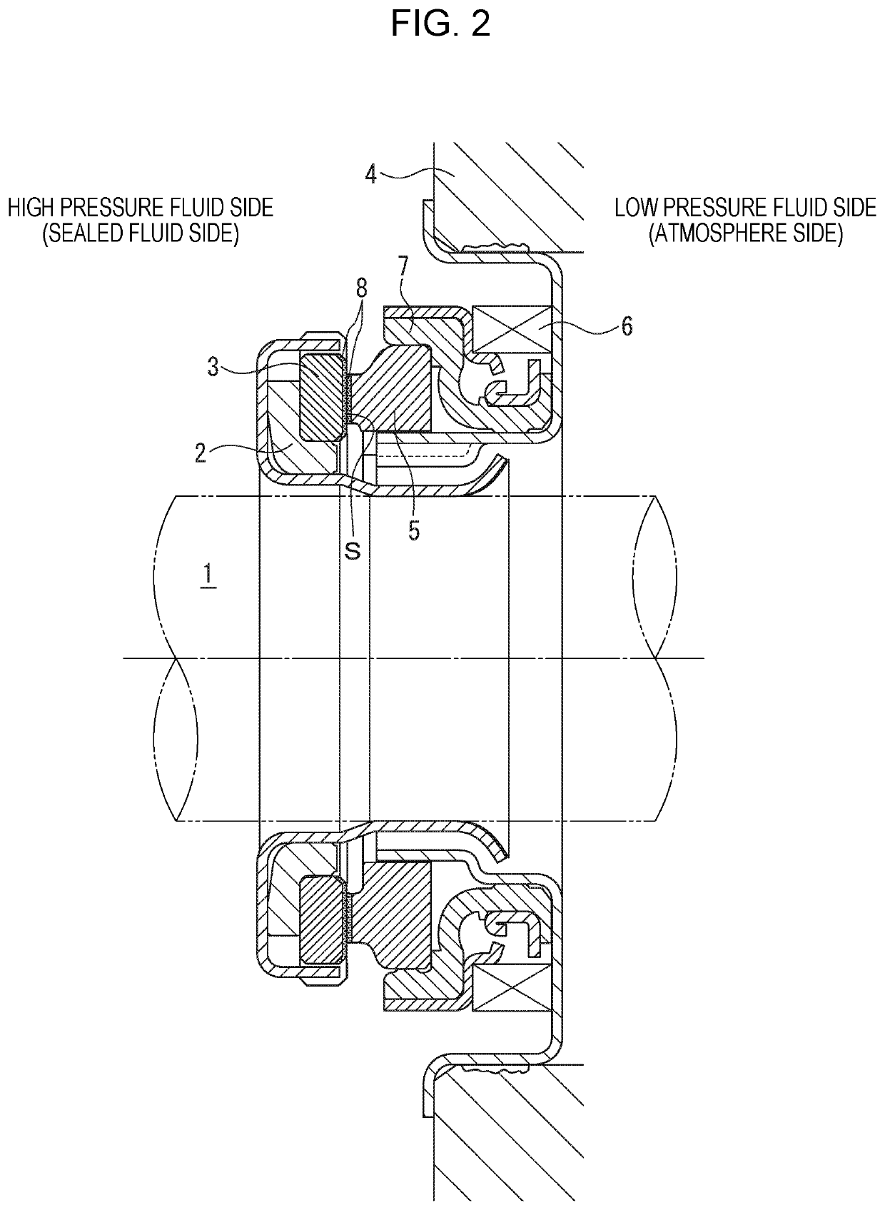
[0052]The sealing faces S of the annular substrates made of silicon carbide formed for the rotating side seal ring 3 and the stationary side seal ring 5 were processed to be smooth by lapping. In a plasma CVD device, by using a hydrocarbon gas containing no silicon compound, an amorphous carbon film having thickness of 150 nm was laminated on the sealing faces S of the substrates of the rotating side seal ring 3 and the stationary side seal ring 5, and a sliding test was conducted under the following sliding test conditions.

[0053]In this case, content of silicon emitted from the substrates made of silicon carbide as outgassing by plasma treatment and contained in the amorphous carbon film was 0.07 at %.

[0054]The content of silicon in the amorphous carbon film was determined by performing narrow measurement on a smooth portion where a dynamic pressure generation groove, etc. are not processed by the X ray photoelectron spectroscopy (XPS) (PHI Quantera SXM by ULVAC-PHI, INCORPORATED.)...

example 2

[0062]In the state of Example 1, the amorphous carbon film was laminated only on the sealing face S of the substrate of the stationary side seal ring 5. A result of the test conducted under the sliding test conditions of Example 1 will be shown in Table 1.

example 3

[0063]In the state of Example 1, by using a hydrocarbon gas containing no silicon compound, an amorphous carbon film whose content of silicon is 0.24 at % and film thickness is 150 nm was laminated on the sealing faces S of the substrates of the rotating side seal ring 3 and the stationary side seal ring 5. A result of the test conducted under the sliding test conditions of Example 1 will be shown in Table 1.


PUM

PropertyMeasurementUnit
thicknessaaaaaaaaaa
widthaaaaaaaaaa
widthaaaaaaaaaa

Abstract

In an exemplary embodiment, a sliding component includes an annular stationary side seal ring 5 fixed to the stationary side and an annular rotating side seal ring 3 to be rotated together with a rotating shaft, in which by relatively rotating opposing sealing faces S of the stationary side seal ring 5 and the rotating side seal ring 3, a silicate-containing sealed fluid present on one side in the radial direction of the relatively rotating sealing faces S is sealed, wherein an amorphous carbon film 8 formed by using a hydrocarbon gas containing no silicon compound is provided on at least any one of the sealing faces S of the stationary side seal ring 5 and the rotating side seal ring 3, and content of silicon of the amorphous carbon film 8 is 1.5 at % or less.

Description

TECHNICAL FIELD[0001]The present invention relates to a sliding component suitable, for example, as a mechanical seal, a bearing, and other sliding units. In particular, the present invention relates to a sliding component such as a seal ring or a bearing that requires reduction of friction by interposing a fluid between sealing faces, and prevention of leakage of the fluid from the sealing faces.BACKGROUND ART[0002]In order to maintain a sealing property in the long term in a mechanical seal serving as an example of a sliding component, contradictory conditions of “sealing” and “lubrication” have to be compatible with each other. In particular, in recent years, for environmental measures, etc., there is a growing demand to furthermore reduce friction and extend the life while preventing leakage of a sealed fluid.[0003]A method of reducing friction can be achieved by providing a dynamic pressure generation mechanism between sealing faces by rotation, and sliding in a state where a l...

Claims


Application Information

Patent Timeline
Patent Type & Authority Applications(United States)
IPC IPC(8): F16J15/3284F16J15/00
CPCF16J15/3232F16J15/002F16J15/3284C23C16/27F16J15/34F16J15/3412F16J15/3496F16C33/72
Inventor ITADANI, MASATOSHISUNAGAWA, KAZUMASAOKADA, TETSUZOCHIBA, KEIICHIKIRYU, KENJIKIMURA, TADAHIROKOGA, AKIKO
Owner EAGLE INDS
Learn More