
Drill assembly and valve

a technology of drill assembly and valve, which is applied in the direction of portable drilling machines, manufacturing tools, mechanical equipment, etc., can solve the problems of reducing the reliability of compressed air supplied at the required pressure, affecting the efficiency of drillers, and increasing the cost of extending the required infrastructure, so as to achieve amelioration, mitigate or overcome the

Active Publication Date: 2020-05-28
UGT GRP PTY LTD
View PDF0 Cites 2 Cited by
  • Summary
  • Abstract
  • Description
  • Claims
  • Application Information

AI Technical Summary

Benefits of technology

This invention is for a drill assembly and valve that solves problems with previous drill assemblies and valves. The drill can change modes: forward, neutral, and reverse. In reverse mode, the drill can be decoupled from the drill bit, allowing for easier replacement of drill steel. The valve has a throttle for rapid adjustment of fluid flow and a dump valve for safe replacement of drill steel. These features make the drill assembly and valve more efficient and easy to use.

Problems solved by technology

However, as the mine deepens the cost to extend the required infrastructure is considerable.
Furthermore, the driller will often experience a drop of efficiency as the reliability of compressed air supplied at the required pressure decreases with an increase in drilling depth.
Another disadvantage of pneumatically driven drills is the noise made by the drills.
In the close confines of a mine shaft this noise is amplified rendering the work conditions very difficult particularly if drilling for a prolonged period of time.
The use of compressed air also generates significant dust in the confines of the mine shaft.
This, together with the noise created by the drill, contributes significantly to the pollution in the shaft.
Another problem with drills used for rock drilling is that the drills only have a forward motion and a neutral motion.
This can prove inefficient when drilling a deep hole which, after reaching a certain depth, requires a longer drill steel to be used.
As the drill steel is threadingly received relative to the drill it is not possible to rotate the drill steel relative to the drill in a manner which will release the drill steel while the drill steel remains in the hole.
As a result air support legs face the same issues as pneumatically driven drills in relation to reliability of compressed air at the required pressure, in addition to the costs associated with the required infrastructure to supply the air.
Fluid activated support legs typically use water and generally are not configurable to provide telescopic adjustment.
This can be significant as it limits the scope of the support leg before it requires repositioning, but it also renders the leg slow / difficult to retract to a smaller size.

Method used


Image

  • Drill assembly and valve
  • Drill assembly and valve
  • Drill assembly and valve

Examples


Embodiment Construction

[0055]Referring to the figures, the invention according to an embodiment is in the form of a drill assembly 11. In this embodiment the drill assembly 11 comprises a drill 13 particularly adapted to be used for rock drilling in underground mining. However, it is to be appreciated that the present invention may have other applications such as a jackhammer and as an impact wrench. These and similar alternatives are considered to be within the scope of this invention.

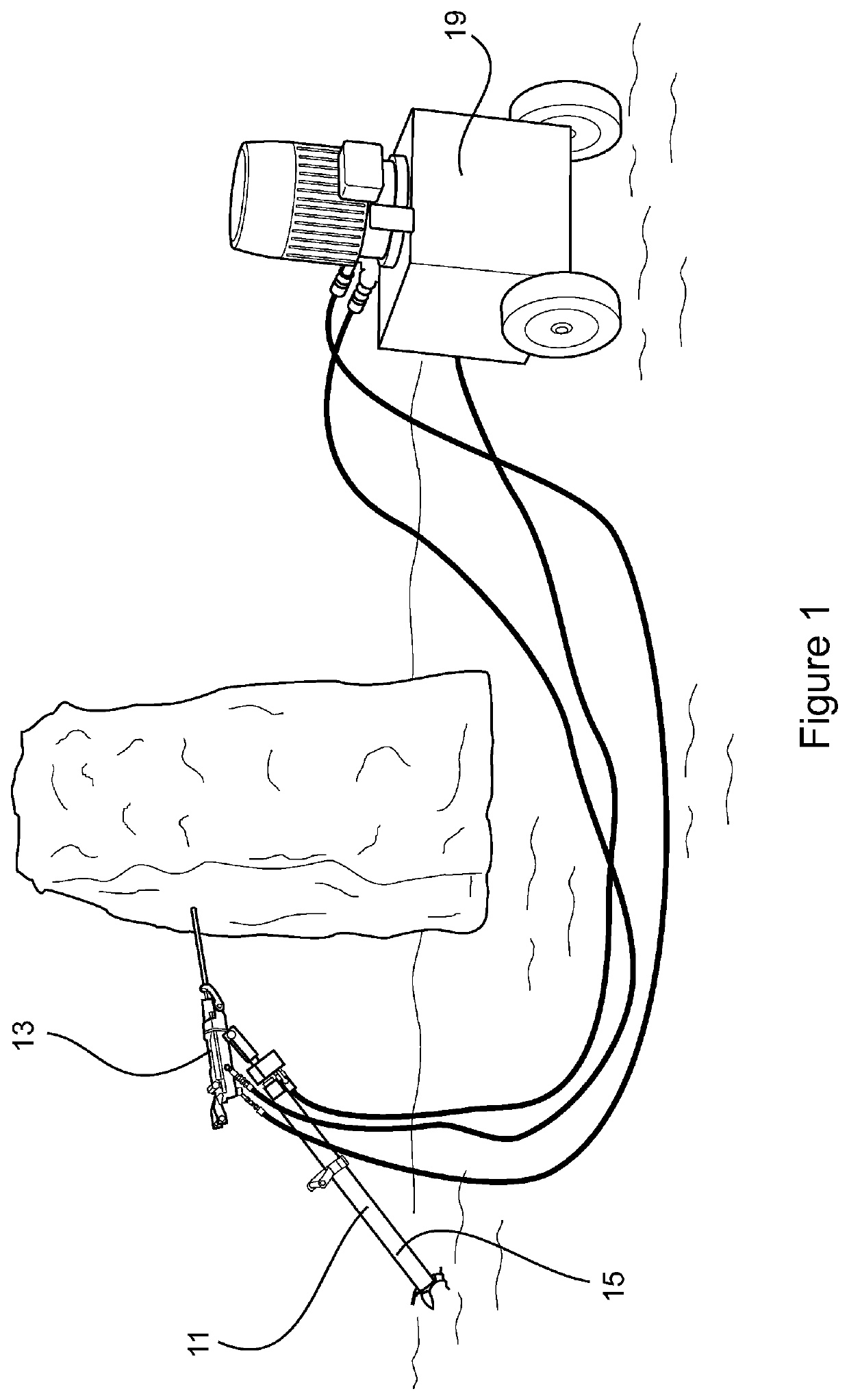
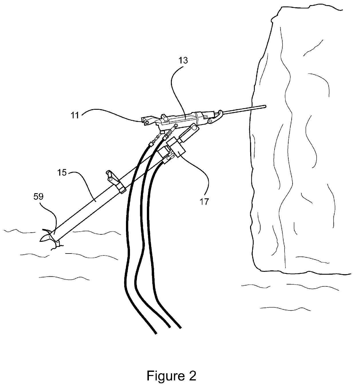
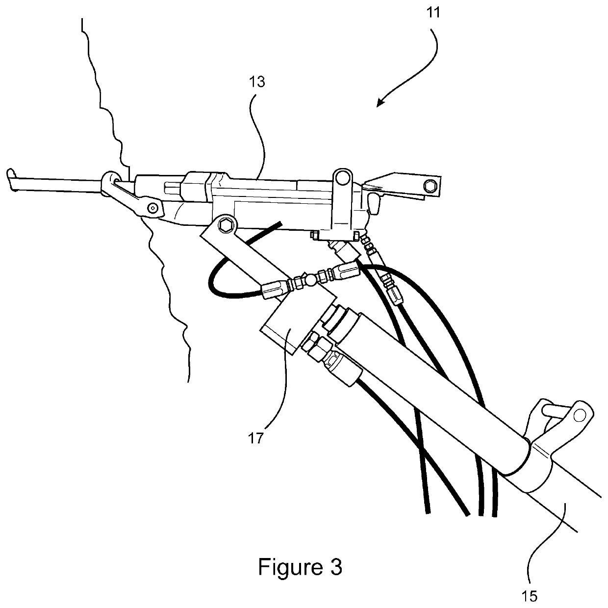
[0056]As shown in FIGS. 1 to 3 the drill assembly 11 comprises the drill 13, a support in the form of a support leg 15 for supporting the drill 13, and a valve 17 which releasably secures the drill 13 to the support leg 15.

[0057]The valve 17 controls the flow of fluid from a pump means, which in this embodiment is in the form of a portable hydraulic power pack 19, to the drill 13 and support leg 15. In this embodiment the hydraulic power pack 19 provides hydraulic power to the drill assembly by supplying and receiving fluid...


PUM

PropertyMeasurementUnit
pressureaaaaaaaaaa
rotational forceaaaaaaaaaa
forceaaaaaaaaaa

Abstract

The present invention provides a drill assembly that includes a drill for drilling rock, a support for supporting the drill, and a valve for releasably securing the support and drill together. The valve is adapted to receive a fluid from a pump means and controllably provide the drill and the support with the fluid for operation of the drill and the support.

Description

FIELD OF THE INVENTION[0001]The present invention generally relates to a drill assembly and valve. In particular the invention relates to a hydraulic drill assembly having a drill and support leg for rock drilling.[0002]The invention also has other applications including jack hammers and impact wrenches, and rock breakers.BACKGROUND ART[0003]A rock drill is, as its name suggests, a drill for penetrating rock. These drills are widely used in the mining industry and are often used in very harsh conditions. These drills are typically manually handled by an operator and are combined with a support leg which provides the operator with additional forward thrust and support to drive the drill bit into the rock.[0004]Rock drills are typically a percussion tool with a hammering action. This action provides a short, rapid hammer thrust to a drill bit, allowing the drill to proceed further into the rock with less effort than a conventional drilling action. When drilling rock the hammering acti...

Claims


Application Information

Patent Timeline
Patent Type & Authority Applications(United States)
IPC IPC(8): E21B7/02F16K11/22B23B45/00B25D17/28
CPCE21B7/027B23B45/003F16K11/22B25D17/28E21B7/022E21B11/005B25H1/0035B25D2250/125E21B1/26E21B1/36E21B19/086E21B19/087
Inventor SCOTT, MAX
Owner UGT GRP PTY LTD
Learn More