Soap Dispenser

a dispenser and soap technology, applied in the field of soap dispensers, can solve the problems of causing a significant mess, affecting the service life of the dispenser, etc., and achieve the effect of reducing, reducing or overcoming the mess

Inactive Publication Date: 2012-09-06
SOAPSTREAM
View PDF1 Cites 3 Cited by
  • Summary
  • Abstract
  • Description
  • Claims
  • Application Information

AI Technical Summary

Benefits of technology

[0006]It is an object of this invention to provide a soap dispenser which ameliorates, mitigates or overcomes, at least one disadvantage of the prior art, or which will at least provide the public with a practical choice.
[0007]The invention has also been developed to encourage people to wash their hands and to maintain good hand hygiene. By providing a soap dispenser which addresses the deficiencies of the prior art people will more readily have access to a soapy solution without creating excessive mess.

Problems solved by technology

This leaves a significant mess, particularly if the person is cleaning their hands after gardening or handling greasy machinery.
From an occupational health and safety aspect the cake may be dropped, become encrusted with dirt and present a hazard.
Whilst this solution does keep the area around the basin cleaner, the liquid soap is prone to leak, particularly in warmer conditions.
Furthermore, the dispenser may become blocked, preventing the liquid soap from being dispensed and is easily vandalized and not always in close proximity to the water source.

Method used


Image

  • Soap Dispenser
  • Soap Dispenser
  • Soap Dispenser

Examples


first embodiment

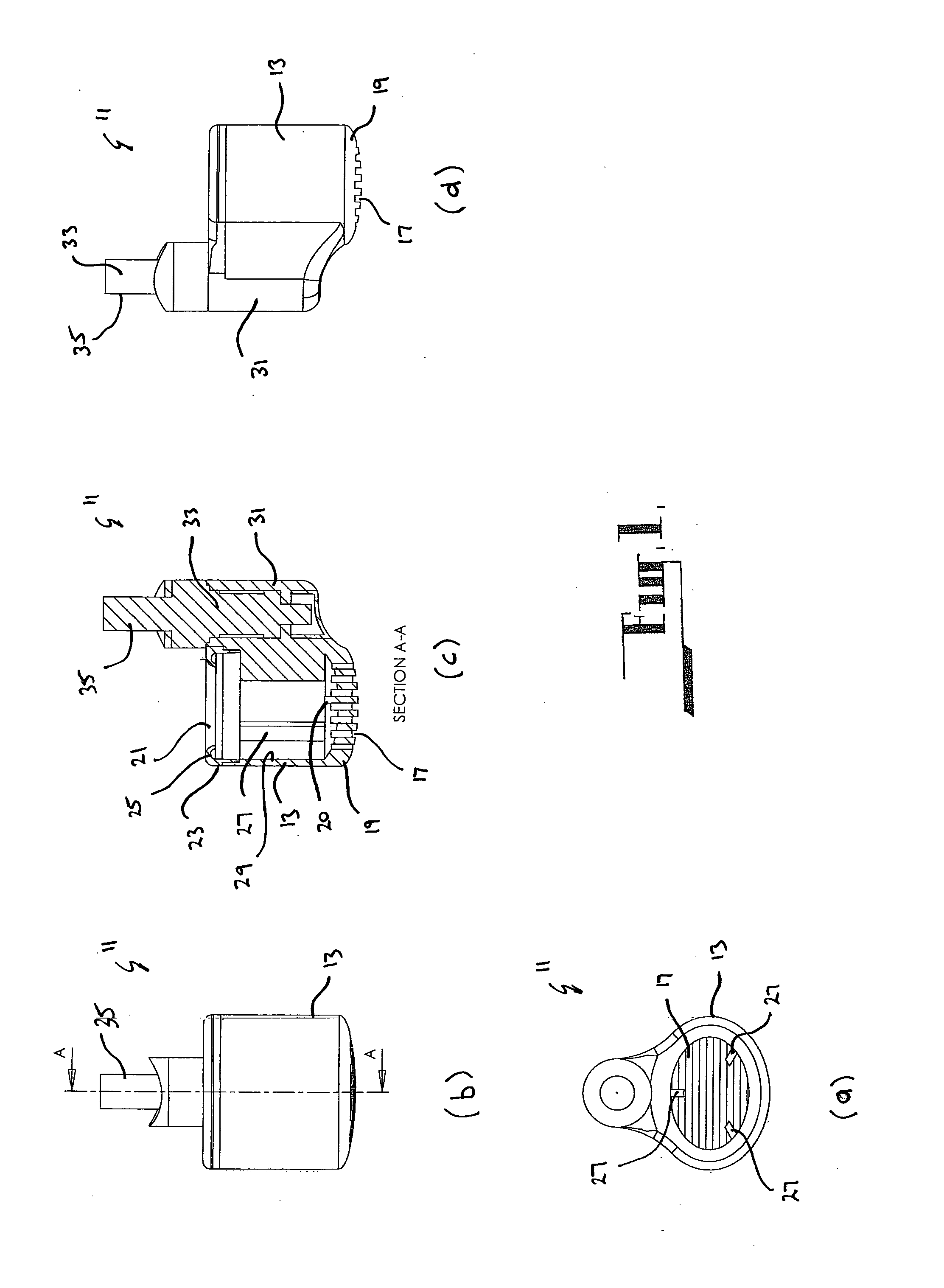
[0074]Referring to FIGS. 1a, b, c, d the invention is in the form of a soap dispenser 11 secured to a fluid outlet, such as a tap 15 for discharging water (the tap is not shown in the figures of the current embodiment). The soap dispenser 11 is adapted to hold a soap cartridge (not shown). When water flows from the tap 15 the water passes into the soap dispenser 11, passing over the soap cartridge. By the time the water passes through and emerges from the soap dispenser 11 the water has mixed sufficiently with the soap cartridge to provide a user of the tap 15 with a soapy solution such that they may wash their hands or other object.

[0075]The soap dispenser 11 comprises a soap holder 13 which receives a soap cartridge (not shown).

[0076]The soap holder 13 comprises a plurality of lower apertures, in the form of slots 17 located in its lower end wall 19. The slots 17 provide a passage for the water to exit the soap dispenser 11. As best seen in FIG. 1c, the lower end wall 19 is of su...

third embodiment

[0088]the invention is illustrated in FIGS. 3a, b, c, d. For convenience features of the soap dispenser 11 that are similar or correspond to features of the soap dispenser 11 of the previous embodiments have been referenced with the same reference numerals.

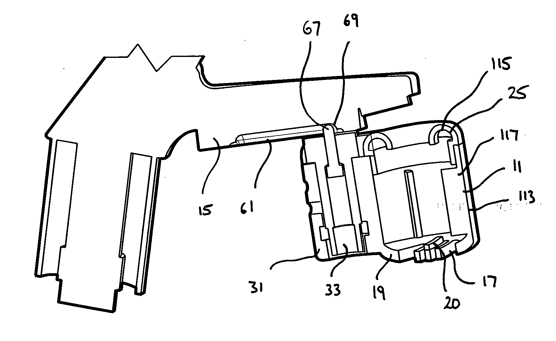
[0089]This embodiment has an alternative connection arrangement to the first and second embodiments whereby the body 31 of the connection arrangement slidingly engages the tap 15. In this embodiment a guide rail 61 is formed integral with the tap 15. The body 31 has an upper portion having a cross sectional slot 63 of complementary shape to that of the guide rail 61. With this arrangement the soap dispenser 11 is retained relative to the tap such that it may slide between the first position and second position.

[0090]The soap dispenser 11 also comprises a retaining means 65 to prevent the soap dispenser 11 detaching from the tap as it slides therealong. The retaining means 65 comprises a projection 67 which is biased upwardly from ...

fourth embodiment

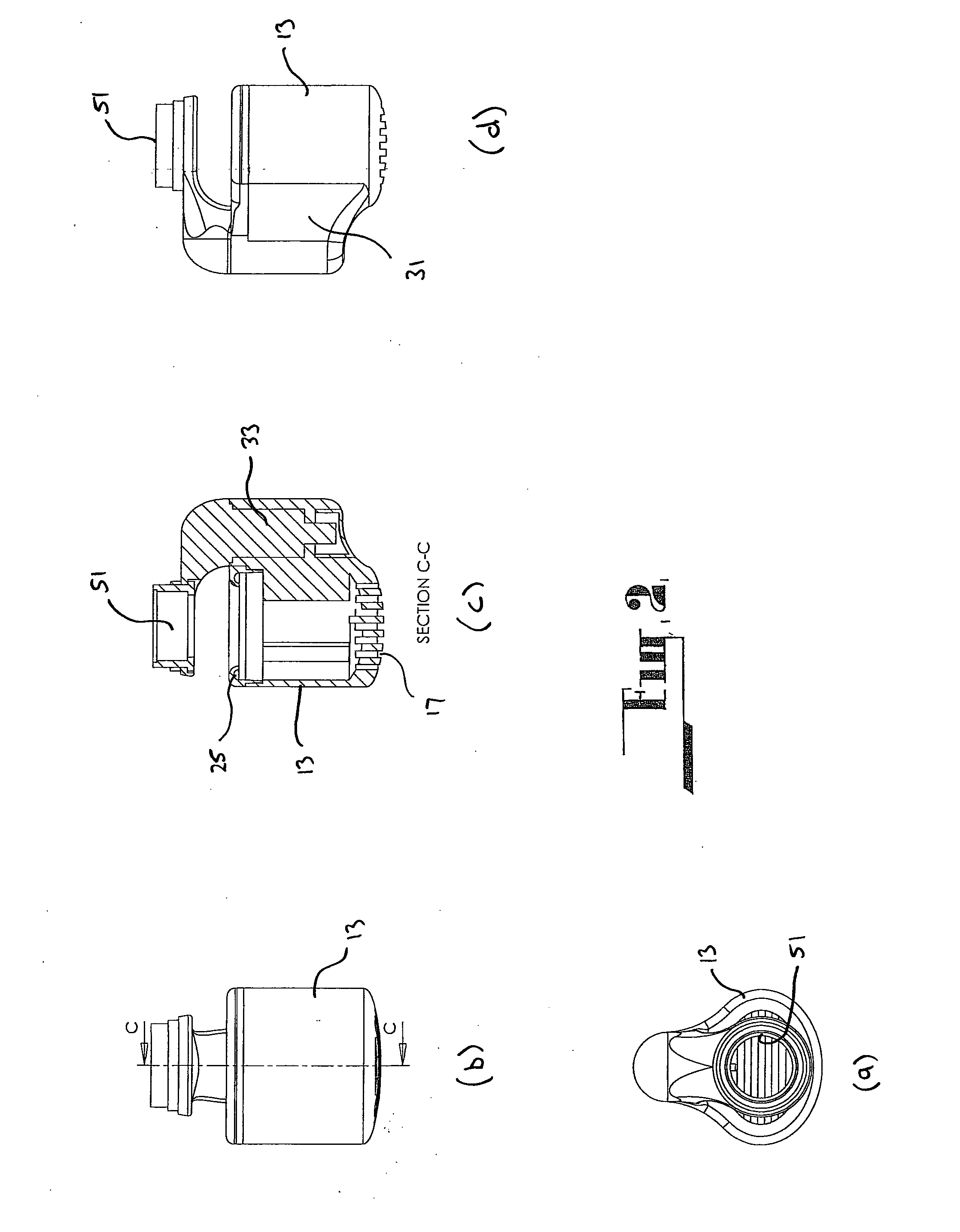
[0092]the invention is illustrated in FIGS. 4a, b, c, d. For convenience features of the soap dispenser 11 that are similar or correspond to features of the soap dispenser 11 of the previous embodiments have been referenced with the same reference numerals.

[0093]This embodiment combines the third embodiment with similar features to that described in the first and second embodiment. In so doing the fourth embodiment takes the soap dispenser 11 of the third embodiment and incorporates a spigot 133 within the body 31. As a result the soap dispenser 11 is slidable relative to the water outlet of the tap 15, as well as being rotatable about the spigot 133. This would assist with the replacement of the soap cartridge.


PUM


Abstract

The present invention provides a soap dispenser (11) for use with a fluid outlet, such as a tap (15). The soap dispenser (11) comprises a soap holder (213) for holding a soap cartridge. The soap holder comprises at least one upper aperture in an upper region through which fluid enters the soap holder, and at least one lower aperture in a lower region through which fluid exits the soap holder. The soap holder incorporates at least one diverting section (25) to divert any fluid moving in an upward direction back into the holder. The soap dispenser also comprises a connection arrangement for connecting the soap holder with respect to the fluid outlet. In use the soap holder is positioned underneath the fluid outlet such that fluid enters the holder through the at least one upper aperture. The fluid then passes over the soap cartridge and exits through the at least one lower aperture to provide a user with a soapy fluid.

Description

FIELD OF THE INVENTION[0001]The present invention generally relates to a soap dispenser. In particular the invention relates to a soap dispenser used in combination with a water outlet such as a tap.BACKGROUND ART[0002]Traditionally, people use a cake of soap to wash their hands. The soap is usually left next to a basin or trough from where a person will use the soap under the flowing water and place it back in position. This leaves a significant mess, particularly if the person is cleaning their hands after gardening or handling greasy machinery. Furthermore there is a transfer of bacteria from one user to the next. From an occupational health and safety aspect the cake may be dropped, become encrusted with dirt and present a hazard.[0003]A solution to prevent significant soiling of the area around the basin / trough is the use of liquid soap. This is typically dispensed using a pump action container. Whilst this solution does keep the area around the basin cleaner, the liquid soap i...

Claims


Application Information

Patent Timeline
IPC IPC(8): B05B7/26E03C1/046A47K5/08
CPCE03C1/0465E03C1/046Y10T137/9464
Inventor GREGORY, KEITH ALWYN
Owner SOAPSTREAM
Why Eureka
Try Eureka