
Flow reactor

a flow reactor and flow technology, applied in the preparation of isocyanic acid derivatives, organic chemistry, products, etc., can solve the problem of limited amount of processing at a time, and achieve the effect of ensuring safety

Active Publication Date: 2020-05-07
KANEKA CORP
View PDF0 Cites 1 Cited by
  • Summary
  • Abstract
  • Description
  • Claims
  • Application Information

AI Technical Summary

Benefits of technology

The invention allows for safe connection of lines in a vessel where a reactor unit and fluid are housed. Even if there is a leak at the line connection, the leak remains within the vessel, ensuring safety.

Problems solved by technology

The micro-flow reactor has a problem that only a limited amount can be processed at a time.

Method used


Image

  • Flow reactor
  • Flow reactor
  • Flow reactor

Examples


first example

1 FIRST EXAMPLE

[0035][First step: Compound A+Compound B→Compound C];

[0036][Second step: Compound D→Compound E]; and

[0037][Third step: Compound C+Compound E→Compound F]

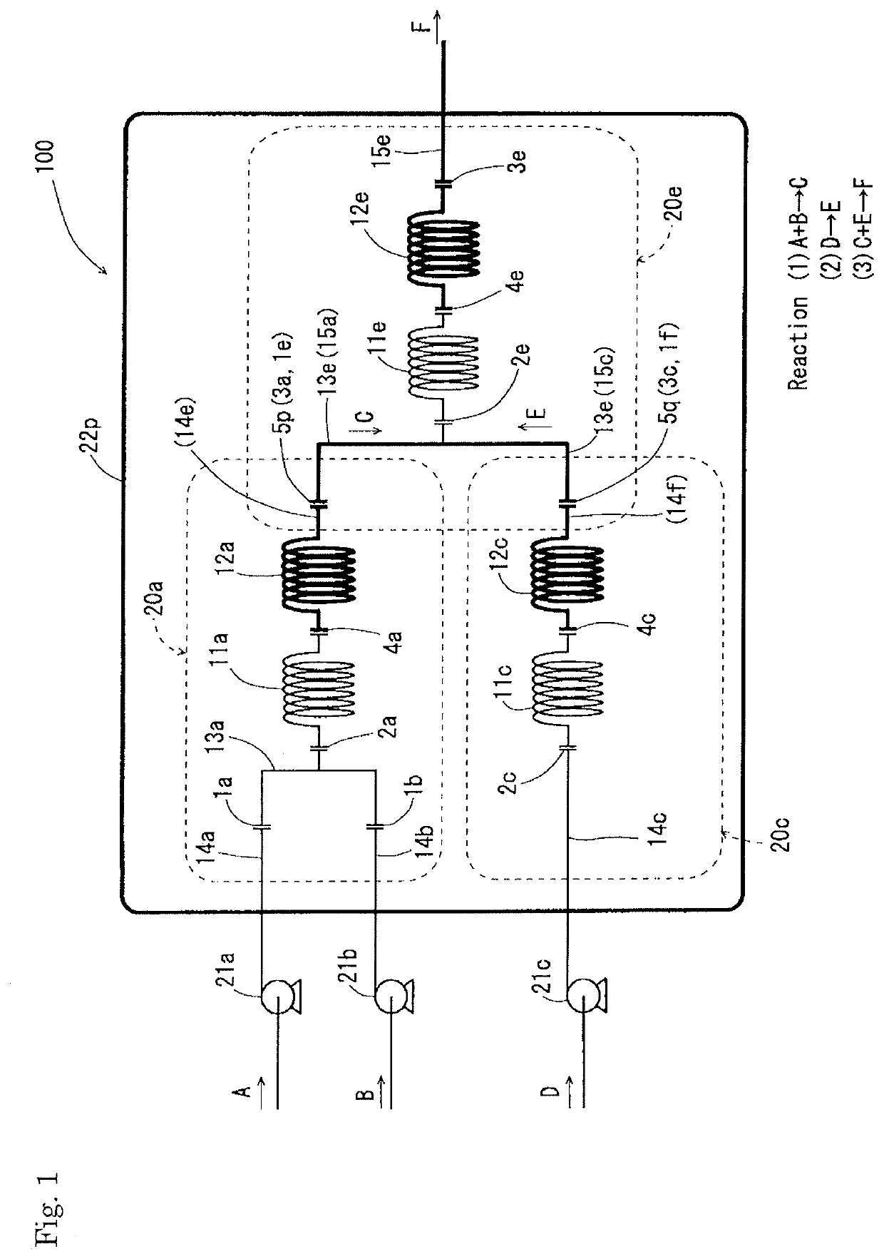
[0038]FIG. 1 is a schematic view showing a first example of the flow reactor of the present invention, the first example having a line set assuming the above three-step reaction.

[0039]Specifically, a flow reactor 100 of FIG. 1 includes a line structure 20a for performing the first step, a line structure 20c for performing the second step, and a line structure 20e for performing the third step. The line structure 20c for the second step is characterized by feeding only one kind of raw material (D) (hereinafter, a line structure for feeding one kind of raw material may be referred to as an A-type line structure). The line structure 20a for the first step and the line structure 20e for the third step are common in that two kinds of raw materials are mixed to be allowed to react (hereinafter, a line structure for feeding a...

second example

2 SECOND EXAMPLE

[0044][First step: Compound K+Compound L→Compound M]

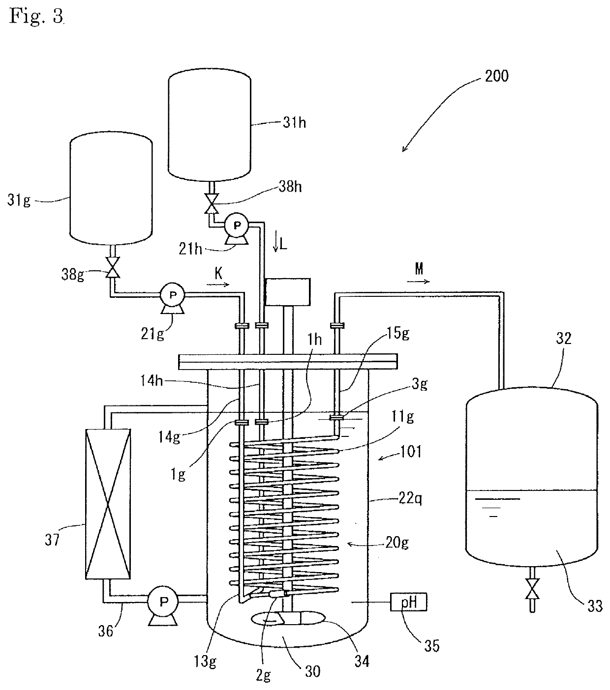
[0045]The basic concept of the flow reactor shown in the first example is the same even if the assumption reaction, that is, the entire line set changes. A flow reactor 101 in FIG. 2 has a line set assuming the above the first step reaction, and thus includes a single B-type line structure 20g for two kinds of raw materials. Specifically, the flow reactor 101 includes a single line structure composed of two raw material feeding lines 14g and 14h, a reactor unit 11g to react raw materials (K and L) fed from the raw material feeding lines 14g and 14h, a discharge line 15g to discharge a reaction product produced in the reactor unit 11g, and a mixing unit 13g to mix the raw materials (K and L) fed from the raw material feeding line 14g and 14h and send the mixture to the reactor unit 11g.

[0046]In the example of FIG. 2 as well, the line structure has two or more attachable and detachable parts as a whole. Specifically,...


PUM

PropertyMeasurementUnit
Diameteraaaaaaaaaa
Diameteraaaaaaaaaa
Flow rateaaaaaaaaaa

Abstract

The purpose of the present invention is to provide a flow reactor that can ensure safety even if leakage occurs at the connections of the lines. The flow reactor of the present invention is characterized by including one or more line structures, each of the line structures including a raw material feeding line, a reactor unit to react a raw material fed from the raw material feeding line, and a discharge line to discharge a reaction product produced in the reactor unit, wherein the flow reactor includes a vessel in which part or all of the reactor unit and a fluid are accommodated to be capable of being in contact with each other, wherein each of the line structures includes two or more attachable and detachable connections, and wherein at least one of the attachable and detachable connections is accommodated in the vessel.

Description

TECHNICAL FIELD[0001]The present invention relates to a flow reactor.BACKGROUND ART[0002]A micro-flow reactor is a chemical reaction apparatus generally utilizing a microchannel in the order of submillimeter as a reaction field. The micro-flow reactor has attracted attention in recent years because it has specific effects, due to the micro reaction field, such as high-speed mixing performance (for example, when two liquids are mixed in a micro-space, the substance diffusion distance in the two liquids decreases, resulting in shortening the time of mass transfer movement), heat removal efficiency (since the reaction field is small, thermal efficiency is extremely high and temperature control is easy), reaction control performance, interface control performance, or the like. In addition, it is expected that the technology of the micro-flow reactor provides various effects such as improved safety and significantly reduced cost of equipment along with downsizing of the whole process, pr...

Claims


Application Information

Patent Timeline
IPC IPC(8): B01J19/24C07C263/10
CPCB01J19/0093B01J2219/24B01J2219/00166B01J2219/00085B01J19/0013C07C263/10B01J19/24B01J8/0496B01J2219/00795B01J2219/00867B01J2219/00869B01J19/243B01J19/242B01J19/2425B01J19/002B01J2219/00256B01J2219/00988Y02P20/141C07C265/02
Inventor OZASA, SHIORIOHISHI, TAKAHIROYASUKOUCHI, HIROAKI
Owner KANEKA CORP
Learn More