
Punching bag retention apparatus

a retention apparatus and bag technology, applied in the field of punching bag retention apparatus, can solve the problems of affecting the effectiveness of the use of the bag, and breaking the user's momentum and concentration, so as to achieve effective follow-up strikes, work on the footwork skills of the user, and high strike rate

Inactive Publication Date: 2020-05-07
MAXWELL DAVID WILLIAM IDEN
View PDF0 Cites 0 Cited by
  • Summary
  • Abstract
  • Description
  • Claims
  • Application Information

AI Technical Summary

Benefits of technology

This patent is about a punching bag retention apparatus that provides a flexible and adjustable way to hold different sized punching bags in place during training. The apparatus includes a tether with limited elasticity to absorb the force of the user's strike and prevent uncomfortable movements. Other interface elements like D-rings and tri-rings allow for easy connection and disconnection of various clips. The apparatus also includes a carriage that acts as an energy absorption and braking mechanism to reduce discomfort for the user while still allowing them to move around the bag. The invention is portable and adjustable, making it easy for users to use with different bags and in various training environments. The length of the tether can be adjusted to suit different training needs, and the apparatus allows for effective strikes and effective training.

Problems solved by technology

However the energy transferred to the punching bag will induce a swinging motion in the bag after the first strike, causing it to swing away from the user.
This somewhat unpredictable motion induced in the bag can break the user's momentum and concentration, forcing them to pursue the bags motion with follow-up strikes in a manner that does not simulate the actions of a real opponent.
For novice users the swinging motion of the bag can be off-putting and make these bags difficult to use effectively.
This approach is effective, but precludes solo training sessions which can be a particular problem for users with home gym training areas.
However this approach requires a large and heavy weight to be located underneath the bag, or an eyelet to be permanently bolted through the floor of a training area.
This is sometimes unwelcome—particularly in the case of multipurpose training areas with these elements forming a tripping hazard if the punching bag is to be removed and the same space is to be used for alternative pursuits.
Furthermore, it is also common for various types of bags to lack any appropriate connection or attachment system which allows for the use of these types of floor anchors.

Method used


Image

  • Punching bag retention apparatus
  • Punching bag retention apparatus
  • Punching bag retention apparatus

Examples


Embodiment Construction

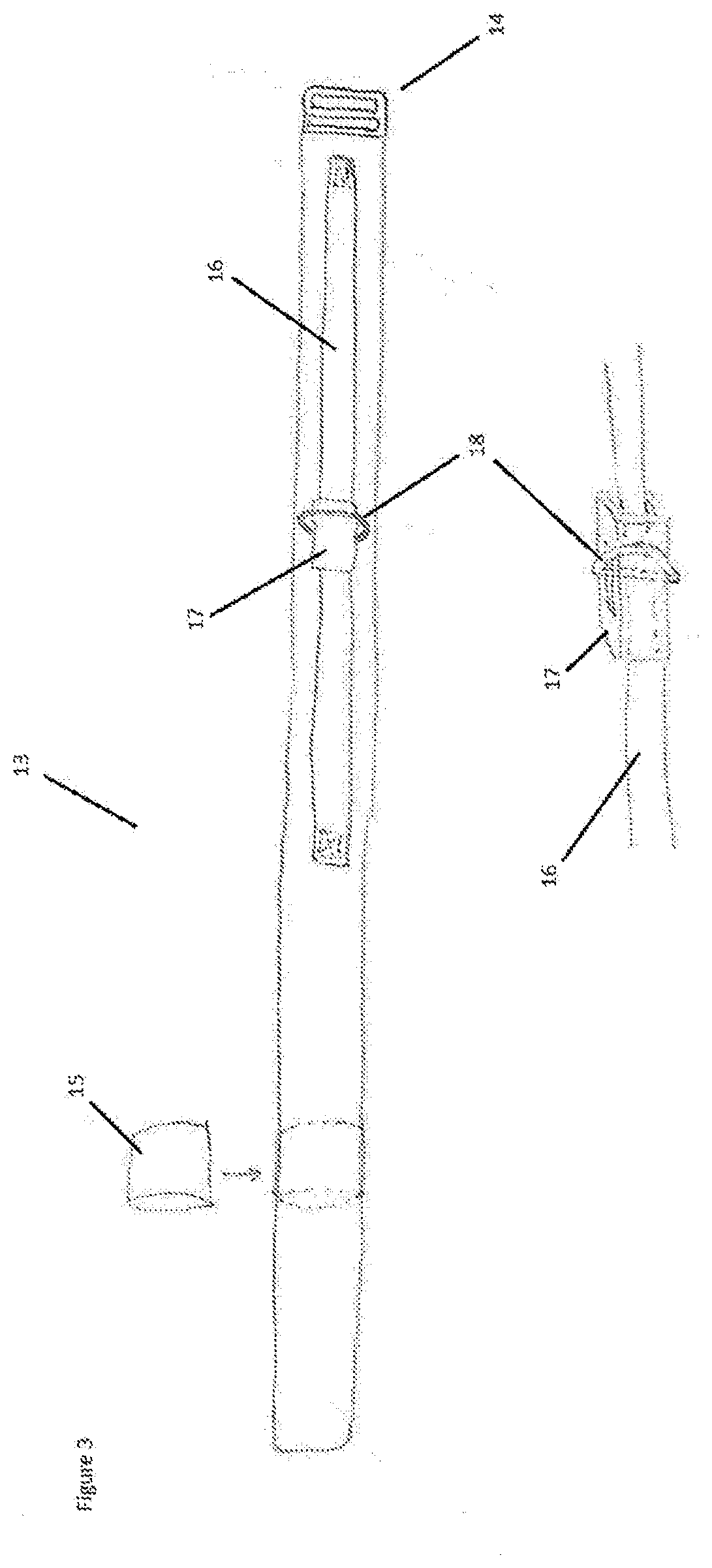
[0057]FIGS. 1 through 4 show the provision of a punching bag retention apparatus as provided in accordance with a preferred embodiment of the invention. This apparatus consists of the user engagement structure shown in FIG. 1 connected to the tether shown in FIG. 2 which is in turn connected to the bag engagement structure shown in FIG. 3.

[0058]In the embodiment illustrated with respect to FIG. 1 the punching bag retention apparatus incorporates a user engagement structure formed as a belt 1. This belt is arranged to be worn around the waist or hips of a user and includes a buckle 2 and eyelets 3 to adjust the circumference of the belt on the user. Also included is a sleeve 4 to retain excess belt material once tightened around a user, in addition to a D-ring 5 to facilitate a connection with the tether of FIG. 2.

[0059]As can be seen from FIG. 1 a single D-ring 5 is provided in conjunction with the user engagement belt. Those skilled in the art should appreciate that in other embodi...


PUM


Abstract

In one aspect the invention provides a punching bag retention apparatus which includes a bag engagement structure, and a user engagement structure. This retention apparatus also includes a tether defining a bag end and a user end, the bag end of the tether being arranged to connect to the bag engagement structure, and the user end of the tether being arranged to connect to the user engagement structure.

Description

FIELD OF THE INVENTION[0001]This invention relates to a punching bag retention apparatus. In various embodiments the invention may be used to control the movement of a punching bag when struck by a user.BACKGROUND OF THE INVENTION[0002]Boxing and other martial arts art are sports pursued competitively by athletes and exercise activities undertaken for health and fitness reasons.[0003]One piece of equipment used in these pursuits is a large punching bag used to simulate strikes to the body of an opponent. These bags normally have a cylindrical form approximately a metre in height with a diameter ranging from 20-50 cm, with the bag being filled with anywhere from 20 to 100 kg of resilient stuffing material. These bags are generally suspended from the ceiling of a training area and are free to swing under the impacts of the user's strikes. Suspending the bag in this way increases the angles of attack open to a user for their strikes.[0004]These bags are effective in simulating body blo...

Claims


Application Information

Patent Timeline
IPC IPC(8): A63B69/20
CPCA63B69/20A63B69/26A63B21/4009A63B2220/53A63B2244/102A63B2209/00A63B2244/10A63B2225/50A63B2220/833A63B2225/09A63B2220/80
Inventor MAXWELL, DAVID WILLIAM IDEN
Owner MAXWELL DAVID WILLIAM IDEN
Learn More