Eureka AIR delivers breakthrough ideas for toughest innovation challenges, trusted by R&D personnel around the world.

Lavatory monument for aircraft

a lavatory and aircraft technology, applied in the field of aircraft, can solve the problems of not being able to simply replace a part with something he or she sees in non-aircraft markets, not being able to simply remove and replace the backsplash, and not being able to solve the problem of easy to replace the backsplash

Inactive Publication Date: 2020-04-30
THE BOEING CO
View PDF0 Cites 10 Cited by
  • Summary
  • Abstract
  • Description
  • Claims
  • Application Information

AI Technical Summary

Benefits of technology

The patent describes an aircraft with a removable lavatory monument inside the fuselage. The monument includes a floor panel and a toilet connected to it. The fixtures in the lavatory can be individually removed and replaced without needing to modify the overall structure of the monument. This design allows for easy customization and maintenance of the aircraft's interior.

Problems solved by technology

Because of these extensive regulations, a technician or engineer cannot simply replace a part with something he or she sees in non-aircraft markets.
However, this regulatory and design scheme results in a problem: if even a single component of the inside of the lavatory requires replacement, such as if a merely decorative flaw were to appear in a backsplash, then the entire lavatory monument (walls, floor, toilet, sink, everything) has to be removed and a new lavatory monument installed.
It is not possible to simply remove and replace the backsplash.
This problem is not easily solved because the heavy regulatory environment leads engineers to design entire lavatory monuments to meet regulatory requirements.
To date, no solution to this problem has been presented.
Common interface points on each of the plurality of lavatory fixtures are unchangeable with respect to the lavatory monument.

Method used


Image

  • Lavatory monument for aircraft
  • Lavatory monument for aircraft
  • Lavatory monument for aircraft

Examples


Embodiment Construction

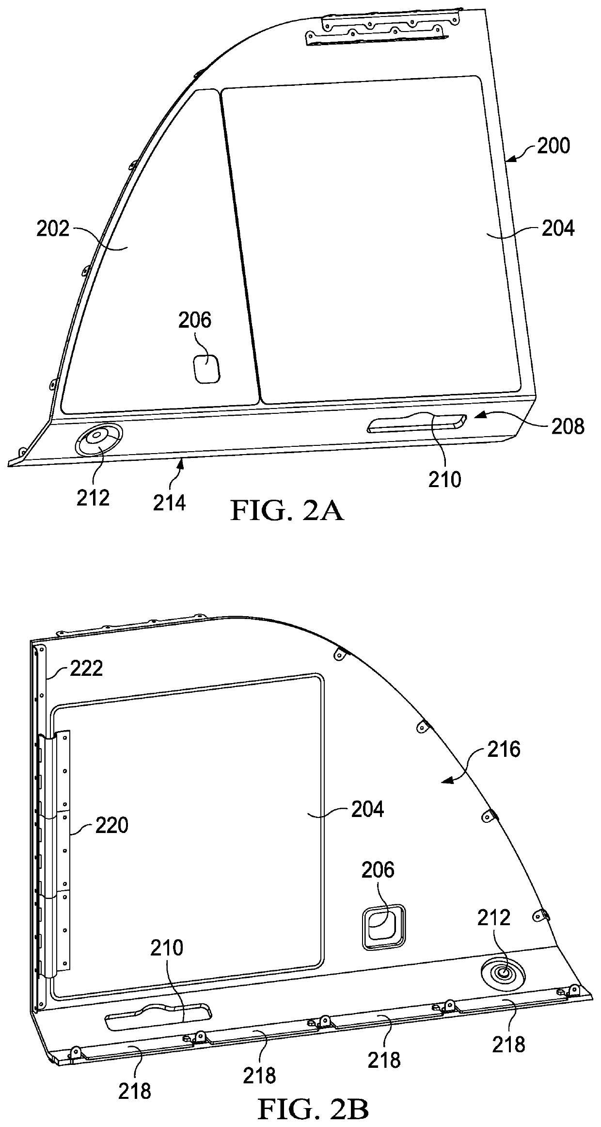
[0031]The different illustrative embodiments recognize and take into account a number of different considerations. For example, the illustrative embodiments recognize and take into account that, due to the heavy regulatory environment of aircraft, aircraft lavatory monuments are not modular. In other words, while the monument itself is replaceable, the components and parts inside the lavatory are not.

[0032]In an effort to support customers with increasing demand for customization and features, the illustrative embodiments provide for an aircraft lavatory monument design was developed with the intention of providing additional feature selections, which would allow customers to differentiate their brands and provide increased levels of service. To accomplish the goal of allowing maximum customization with minimal engineering impact, a modular design system was developed. The modular nature of the concept allows multiple sub-assemblies to be removed and replaced without impacting the s...


PUM


Abstract

An aircraft including a lavatory monument. The lavatory monument includes an outboard wall and a shell wall removably connected to the outboard wall, both walls extending radially inwardly relative to a fuselage of the aircraft. The lavatory monument also includes a floor panel connected to and between the outboard wall and the shell wall. The lavatory monument also includes a toilet connected to the floor panel. The lavatory monument also includes a plurality of lavatory fixtures individually removably attached to at least one of: the outboard wall, the shell wall, the floor panel, or the toilet. Each of the plurality of lavatory fixtures is individually removable. Common interface points on each of the plurality of lavatory fixtures are unchangeable with respect to the lavatory monument.

Description

CROSS-REFERENCE TO RELATED APPLICATIONS[0001]This application is related to U.S. Pat. No. ______ filed concurrently with this application, and titled “Improved Aft Wall for a Lavatory Monument of an Aircraft”, Attorney Docket No. 18-0455-US-NP; this application is related to U.S. Pat. No. ______ filed concurrently with this application, and titled “Modular Faucet System for Aircraft”, Attorney Docket No. 18-0497-US-NP; the entire disclosures of which are incorporated by reference herein.BACKGROUND INFORMATION1. Field[0002]The present disclosure relates to aircraft and, more particularly, to aircraft modular lavatory monuments having replaceable fixtures.2. Background[0003]Aircraft are subject to strict regulatory compliance standards in nearly every country in the world. In the United States, the Federal Aviation Administration governs the standards for manufacturing, maintaining, and operating aircraft and ancillary concerns such as operating airports. The Federal Aviation Regulati...

Claims


Application Information

Patent Timeline
Patent Type & Authority Applications(United States)
IPC IPC(8): B64D11/02B64C1/14
CPCB64C1/1423B64C1/1461B64D11/02B64D2011/0046B64D45/0061B60R15/02B60R15/04B61D35/005Y02T50/40
Inventor YOUNG, STEPHEN M.SWANSON, KEVIN GRIFFITH
Owner THE BOEING CO
Why Eureka
Eureka Blog
Learn More