Curable polymer, polymerization liquid, conductive film and organic light emitting element
a technology of conductive film and polymerization liquid, which is applied in the direction of conductive materials, solid-state devices, and conductors, can solve the problems of already formed layers dissolving, and achieve the effect of improving service life characteristics
- Summary
- Abstract
- Description
- Claims
- Application Information
AI Technical Summary
Benefits of technology
Problems solved by technology
Method used
Image
Examples
example 1
First Curable Polymer Including Macromolecule Doped with Holes>
[Synthesis of Macromolecule of Crosslinkable Polymer]
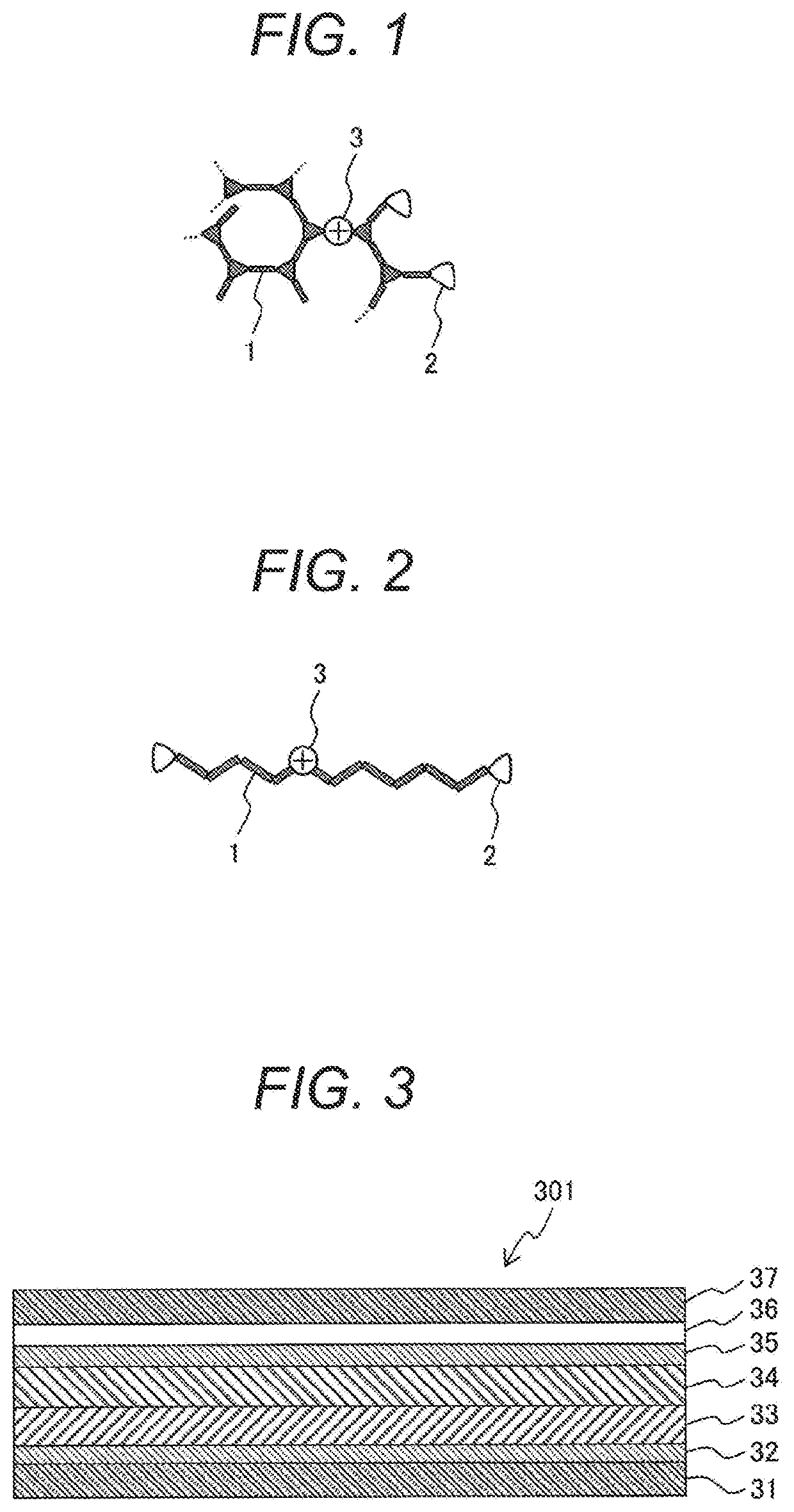
[0058]A crosslinkable polymer was synthesized by polymerizing a linear triphenylamine monomer (the following chemical formula (9)), a branched triphenylamine monomer (the following chemical formula (10)), and an oxetane crosslinking monomer (the following chemical formula (11)) by Suzuki reaction. The linear triphenylamine monomer (chemical formula (9)) has two reaction sites of Suzuki reaction, and forms a main chain by the polymerization. The branched triphenylamine monomer (chemical formula (10)) has three reaction sites of Suzuki reaction, and forms a main chain by the polymerization. The oxetane crosslinking monomer (chemical formula (11)) has one reaction site of Suzuki reaction, and forms a side chain by the polymerization. The crosslinkable oxetane crosslinking monomer (chemical formula (11)) is a monomer having a structure in which a 1-ethyloxetane-1-yl group ...
example 2
Second Curable Polymer Doped with Holes
[0075]A curable polymer was produced in the same procedure as Example 1 except that the crosslinkable linear triphenylamine monomer (chemical formula (9)) in the procedure explained in Example 1 was replaced with 2,7-bis(4,4,5,5-tetramethyl-1,3,2-dioxaborolane-2-yl)-9,9-dioctyl-9H-fluorene (the following chemical formula (12)). The curable polymer is called a second curable polymer.
example 3
Third Curable Polymer Including Macromolecule Doped with Holes
[0076]A curable polymer was produced in the same procedure as Example 1 except that the crosslinkable linear triphenylamine monomer (chemical formula (9)) in the procedure explained in Example 1 was replaced with 2,7-bis(4,4,5,5-tetramethyl-1,3,2-dioxaborolane-2-yl)-N-phenyl-9H-carbazole (the following chemical formula (13)). The curable polymer is called a third curable polymer.
[0077]By the means similar to Example 1, it was confirmed that both the second curable polymer and the third curable polymer were curable polymers doped with holes.
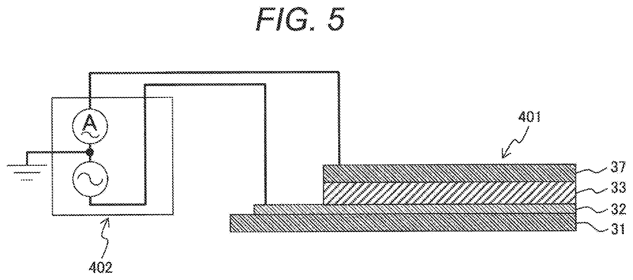
[0078]In a conductive film formed by using the second curable polymer, the hole density was 8±0.5×10¹⁶ [pieces / cm3] when the ionic polymerization initiator concentration was 1.0% by mass and 4±0.4×10¹⁷ [pieces / cm3] when the ionic polymerization initiator concentration was 5.0% by mass.
[0079]In a conductive film formed by using the third curable polymer, the hole density is 1±0.1×10¹⁷ [p...
PUM
| Property | Measurement | Unit |
|---|---|---|
| work function | aaaaa | aaaaa |
| molecular weight | aaaaa | aaaaa |
| capacitance | aaaaa | aaaaa |
Abstract
Description
Claims
Application Information
 - R&D
- Intellectual Property
- Life Sciences
- Materials
- Tech Scout
- Unparalleled Data Quality
- Higher Quality Content
- 60% Fewer Hallucinations
Browse by: Latest US Patents, China's latest patents, Technical Efficacy Thesaurus, Application Domain, Technology Topic, Popular Technical Reports.
© 2025 PatSnap. All rights reserved.Legal|Privacy policy|Modern Slavery Act Transparency Statement|Sitemap|About US| Contact US: help@patsnap.com


