
Image sensor retaining element and method for manufacturing an image sensor retaining element

a technology of image sensor and retaining element, which is applied in the computer field, can solve the problems of stress, shrinkage of adhesive, degradation or loss of the functionality of the connection, etc., and achieve the effects of high cycle time, reduced viscosity, and high degree of flexibility

Inactive Publication Date: 2020-03-26
ROBERT BOSCH GMBH
View PDF2 Cites 3 Cited by
  • Summary
  • Abstract
  • Description
  • Claims
  • Application Information

AI Technical Summary

Benefits of technology

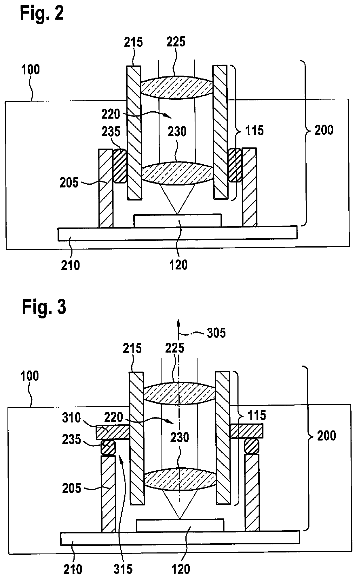
The image sensor retaining element described in this patent reduces mechanical stress and deformation caused by external environmental factors, loads, and chemical influences. The adhesive used between the lens retaining element and the lens support element in the radial direction has an undulated contour, which leads to a seal of the interface between the lens element and the image sensor. This design feat also allows for a targeted selection of deformation areas, and optimizes the overall performance of the image sensor retaining element. Additionally, a device is provided to carry out, control, or implement the steps of the manufacturing process for the image sensor retaining element.

Problems solved by technology

However, it is problematic that stresses occur due to different thermal expansions in the glued joining parts, or stress indices due to the curing characteristics of the adhesive; for an adhesion with long-term resistance, it is essential to reduce this stress in such a way that durability is provided under conditions of use.
Thus, the process of UV precuring and thermal curing of an adhesive may result in adhesive shrinkage.
For this reason, the adhesive should be able to absorb these stresses, since otherwise the adhesion and / or the glued joining partners, for example the lens support element (lens barrel) and the lens retaining element, could deform, as the result of which the functionality of a camera unit would be impaired, or the adhesion could fail, resulting in degradation or loss of the functionality of the connection.
In addition, a soldered joint has a permanently tight connection.
This results in tangential exposure options that may greatly increase the length of the connection.

Method used


Image

  • Image sensor retaining element and method for manufacturing an image sensor retaining element
  • Image sensor retaining element and method for manufacturing an image sensor retaining element
  • Image sensor retaining element and method for manufacturing an image sensor retaining element

Examples


Embodiment Construction

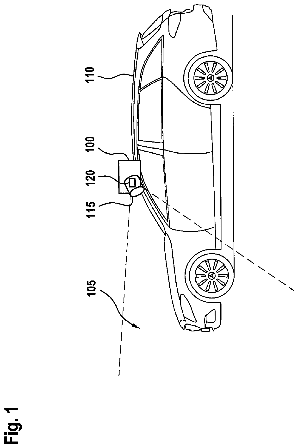
[0044]FIG. 1 shows a schematic view of a camera unit 100 for detecting the surroundings 105 in the detection range of the camera unit according to one exemplary embodiment. According to one exemplary embodiment, camera unit 100 is situated on a vehicle 110, and by way of example includes a lens element 115 and an image sensor 120.

[0045]Camera unit 100 illustrated here is thus used, for example, as part of a driving assistance system for detecting the surroundings of vehicle 110. For example, persons, objects, and / or infrastructure features may be situated in the surroundings 105 of vehicle 110 and may be detected and depicted with the aid of camera unit 100, for example, in order to avoid possible accidents and ensure safe driving of vehicle 110. Accordingly, for camera unit 100 the aim is to implement designs with an approximately cubic configuration and edge lengths smaller than 25 mm. This applies in particular for NRCS systems, but not for front video systems installed in the pa...


PUM


Abstract

An image sensor retaining element for retaining an image sensor and a lens element is described. The image sensor retaining element initially includes a lens retaining element that is designed for accommodating the image sensor and / or an image sensor support. The image sensor retaining element also includes a lens support element (lens barrel) that is designed for accommodating at least one lens element, the lens support element (lens barrel) being situated in the lens retaining element. Lastly, the image sensor retaining element includes an adhesive that is situated between the lens retaining element and the lens support element (lens barrel) in the radial direction. The adhesive has an at least partially undulated contour on an outer circumference of the lens support element (lens barrel) and / or an inner circumference of the lens retaining element.

Description

CROSS REFERENCE[0001]The present application claims the benefit under 35 U.S.C. § 119 of German Patent Application No. DE 102018216387.1 filed on Sep. 26, 2018, which is expressly incorporated herein by reference in its entirety.BACKGROUND INFORMATION[0002]The present invention is directed to a device and a method. A further subject matter of the present invention relates to a computer program.[0003]Adhesive materials that are curable with the aid of UV irradiation and / or by thermal means may be used to fixedly join together a camera lens or a lens element and an image sensor during an alignment of a camera unit. However, it is problematic that stresses occur due to different thermal expansions in the glued joining parts, or stress indices due to the curing characteristics of the adhesive; for an adhesion with long-term resistance, it is essential to reduce this stress in such a way that durability is provided under conditions of use.SUMMARY[0004]An image sensor retaining element, a...

Claims


Application Information

Patent Timeline
Patent Type & Authority Applications(United States)
IPC IPC(8): H04N5/225G02B7/02B60R11/04
CPCG03B17/12H04N5/2254G02B7/025B60R11/04G02B7/022G02B7/02H04N23/55G03B17/02G02B7/021
Inventor DIESEL, PETER
Owner ROBERT BOSCH GMBH
Learn More