Fluorescent lamp
- Summary
- Abstract
- Description
- Claims
- Application Information
AI Technical Summary
Benefits of technology
Problems solved by technology
Method used
Image

Examples
Embodiment Construction
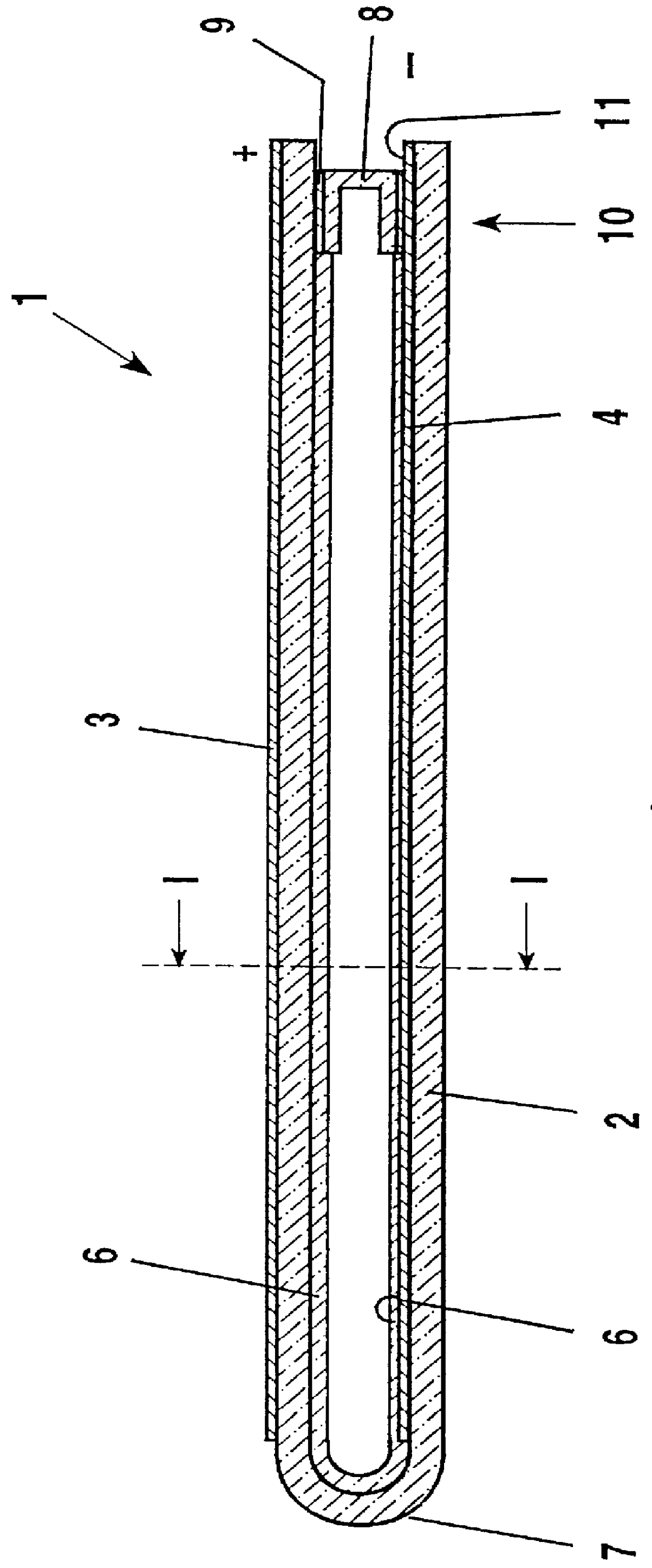
It is the object of the present invention to eliminate the said disadvantages and to provide a fluorescent lamp which has an improved luminous density.
The basic idea of the invention is based on the finding that, on the one hand, the striking distance of the pulsed, dielectrically impeded discharge is to be as large as possible for a high electric power input. On the other hand, the arrangement of all the electrodes on the outer wall of the discharge vessel is to be avoided, in conjunction with the disadvantages associated therewith. Moreover, as constant a striking distance as possible along the discharge tube is to be aimed at for the pulsed, dielectrically impeded discharge. This is important for ensuring the same starting conditions during operation for all individual discharges (see U.S. Pat. No. 5,604,410 in this regard) along the electrodes. Specifically, it is ensured thereby that the individual discharges are formed in a row along the entire electrode length (assuming an ad...
PUM
 Abstract
Description
Claims
Application Information
 - R&D
- Intellectual Property
- Life Sciences
- Materials
- Tech Scout
- Unparalleled Data Quality
- Higher Quality Content
- 60% Fewer Hallucinations
Browse by: Latest US Patents, China's latest patents, Technical Efficacy Thesaurus, Application Domain, Technology Topic, Popular Technical Reports.
© 2025 PatSnap. All rights reserved.Legal|Privacy policy|Modern Slavery Act Transparency Statement|Sitemap|About US| Contact US: help@patsnap.com