
Method of semiconductor integrated circuit fabrication

a technology of integrated circuits and semiconductors, applied in the direction of semiconductor devices, basic electric elements, electrical equipment, etc., can solve the problems of the inability to meet the requirements of the manufacturing process

Active Publication Date: 2020-03-12
TAIWAN SEMICON MFG CO LTD
View PDF17 Cites 2 Cited by
  • Summary
  • Abstract
  • Description
  • Claims
  • Application Information

AI Technical Summary

Benefits of technology

This approach effectively reduces defects and enhances the quality of FinFET devices by eliminating air pockets, leading to improved electrical performance and reduced short-channel effects.

Problems solved by technology

However, such scaling has also introduced increased complexity to the semiconductor manufacturing process.
However, conventional methods to make FinFET devices may still have certain drawbacks.
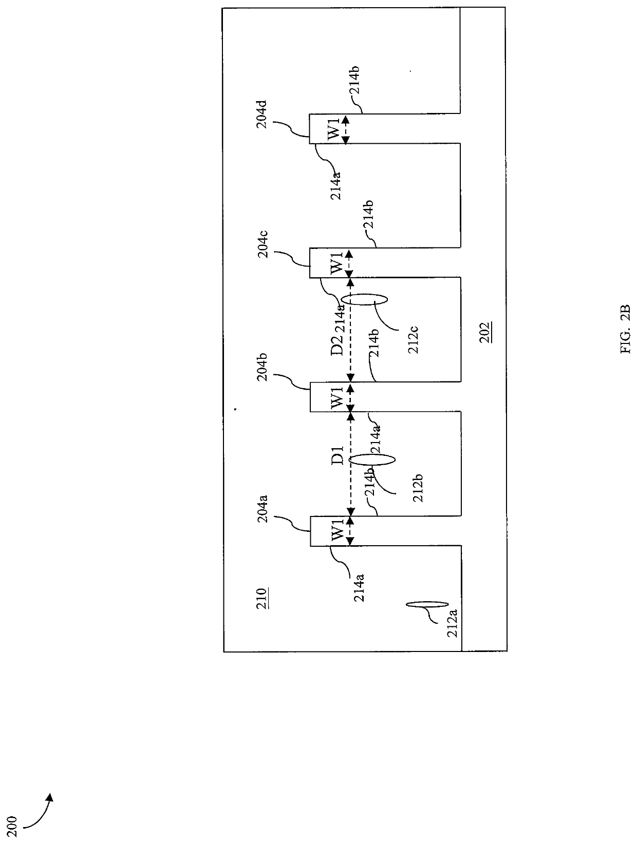
Such gaps may cause various issues during subsequent processes, resulting in flaws in subsequent formed features.
This affects the quality of performance of the FinFET devices.
Thus, the existing techniques have not proved entirely satisfactory in all respects.

Method used


Image

  • Method of semiconductor integrated circuit fabrication
  • Method of semiconductor integrated circuit fabrication
  • Method of semiconductor integrated circuit fabrication

Examples


Embodiment Construction

[0014]The following disclosure provides many different embodiments, or examples, for implementing different features of the provided subject matter. Specific examples of components and arrangements are described below to simplify the present disclosure. These are, of course, merely examples and are not intended to be limiting. For example, the formation of a first feature over or on a second feature in the description that follows may include embodiments in which the first and second features are formed in direct contact, and may also include embodiments in which additional features may be formed between the first and second features, such that the first and second features may not be in direct contact. In addition, the present disclosure may repeat reference numerals and / or letters in the various examples. This repetition is for the purpose of simplicity and clarity and does not in itself dictate a relationship between the various embodiments and / or configurations discussed.

[0015]F...


PUM

PropertyMeasurementUnit
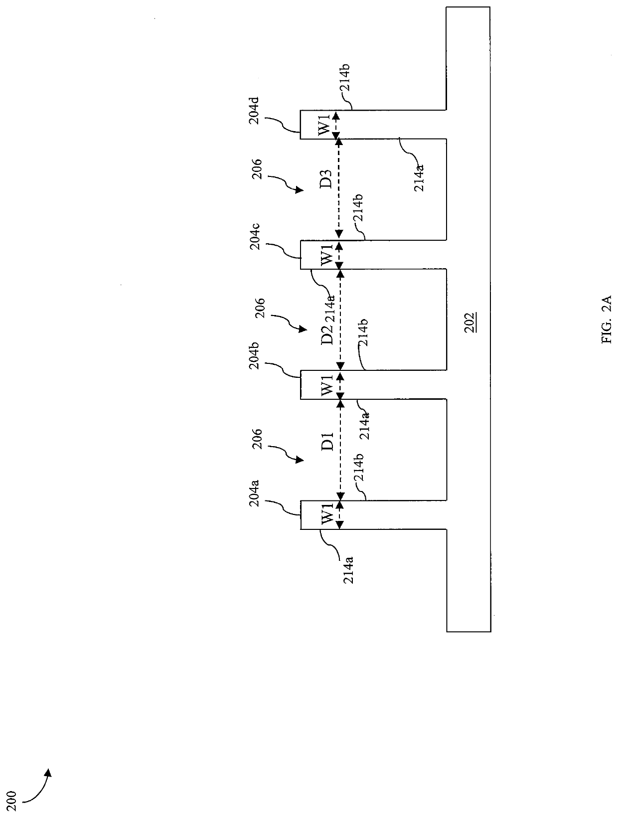
width W1aaaaaaaaaa
width W1aaaaaaaaaa
aspect ratioaaaaaaaaaa

Abstract

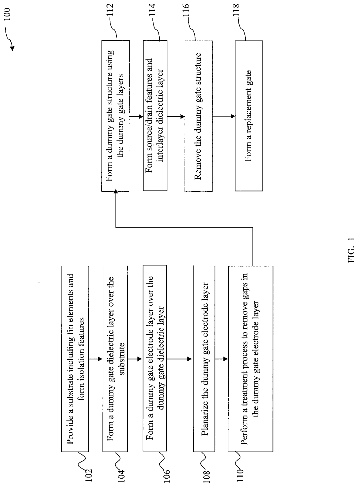
A method includes providing a substrate including a first fin element and a second fin element extending from the substrate, and forming a first layer including a first material over the first and second fin elements, wherein the first layer includes a gap disposed between the first and second fin elements. An anneal process is performed to remove the gap in the first layer, wherein performing the anneal process includes adjusting an energy applied to the first layer during the anneal process. The gap is filled by a portion of the first material around the gap reaching a sub-melt temperature that is different from a melting point of the first material.

Description

PRIORITY DATA[0001]The present application is a continuation application of U.S. patent application Ser. No. 16 / 016,862, filed Jun. 25, 2018, issuing as U.S. Pat. No. 10,483,170, which is a continuation application of U.S. patent application Ser. No. 15 / 282,981, filed Sep. 30, 2016, now U.S. Pat. No. 10,008,418 entitled “METHOD OF SEMICONDUCTOR INTEGRATED CIRCUIT FABRICATION”, each of which is hereby incorporated by reference in its entirety.BACKGROUND[0002]The electronics industry has experienced an ever increasing demand for smaller and faster electronic devices which are able to support a greater number of increasingly complex and sophisticated functions. Accordingly, there is a continuing trend in the semiconductor industry to manufacture low-cost, high-performance, and low-power integrated circuits (ICs). Thus far these goals have been achieved in large part by scaling down semiconductor IC dimensions (e.g., minimum feature size) and thereby improving production efficiency and ...

Claims


Application Information

Patent Timeline
Patent Type & Authority Applications(United States)
IPC IPC(8): H01L21/8238H01L29/66H01L21/324H01L21/268H01L21/02H01L21/8234
CPCH01L29/66795H01L21/268H01L21/823431H01L29/66545H01L21/823878H01L21/02592H01L21/823828H01L21/324H01L21/823481H01L21/02532H01L21/3247H01L21/823821
Inventor YU, DE-WEILO, CHIA PINGYAO, LIANG-GICHANG, WENGYEO, YEE-CHIAFANG, ZIWEI
Owner TAIWAN SEMICON MFG CO LTD
Learn More