
Catadioptric System for Mid-Wave Thermal Imaging Equipment

a technology of thermal imaging equipment and catadioptrics, applied in the field of optoelectronics and infrared engineering, can solve the problems of increasing the level of signal attenuation, increasing the error of equipment assembly, and difficulty in assembly and deployment, so as to facilitate equipment deployment and facilitate the effect of equipment deployment, easy fabrication and low quality of optical systems

Active Publication Date: 2020-03-05
VIETTEL GRP
View PDF0 Cites 2 Cited by
  • Summary
  • Abstract
  • Description
  • Claims
  • Application Information

AI Technical Summary

Benefits of technology

The present invention is a catadioptric system for a medium-wave infrared radiation band that uses a special optical system design for a high-resolution cooling thermal image sensor. The system consists of two main components: a relay and a set of mirrors. The relay consists of three lenses made of different materials that help achieve high-quality images at the sensor plane. The set of mirrors is designed to reflect signals from infinity and create a medial image before the relay. The system is compact and easy to assemble and deploy. The technical effect of this invention is that it provides a high-quality image at a resolution of 10 μm pixel and HD resolution, which is compatible with the sensor size of 10 μm resolution (pixel) and HD resolution.

Problems solved by technology

However, the disadvantage of the invention is the use of many optical elements that lead to difficulties in assembly and deployment.
Besides, many optical elements increase the level of signal attenuation when passing through the optical system and increase the error of equipment assembly.
However, the disadvantage of the invention is that the quality of the optical system is not high, the design cannot be used for cooling sensors with cold shield.
However, the authors do not mention the parameters as well as the quality of the optical system image.

Method used


Image

  • Catadioptric System for Mid-Wave Thermal Imaging Equipment
  • Catadioptric System for Mid-Wave Thermal Imaging Equipment
  • Catadioptric System for Mid-Wave Thermal Imaging Equipment

Examples


Embodiment Construction

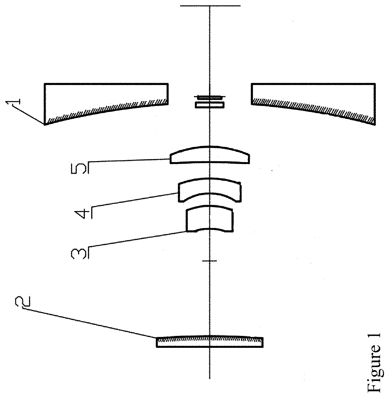
[0014]In FIG. 1: The figure illustrates the main structures of the optical system proposed in this invention. The optical system consists of two main components:

[0015]The first one consists of mirrors 1 (1) and mirror 2 (2) arranged so that the two reflective surfaces are facing each other, in which the mirror 1 (1) is positioned farther from the external environment than the mirror 2 (2). Mirror 1 (1) and mirror 2 (2) have smooth surfaces that meet reflection coefficient greater than or equal to 99%, in which surface distortion of mirror 1 (1) is parabolic, surface distortion of mirror 2 (2) is aspheric. Materials for mirror manufacturing can be chosen freely, but the best result is aluminum. The details of the first component's structure are as follows:

[0016]Mirror surface 1 (1) satisfies:

Z(y)=y2R·⌈1+1-(1+K)·y2R2⌉(1)

[0017]Where: K=−1 is Conic coefficient;[0018]R=−132.74 is the radius of top of the mirror surface.

[0019]Mirror surface 2 (2) satisfies:

Z(y)=y2R·⌈1+1-y2R2⌉+A4·y4+A6·y6+...


PUM


Abstract

The invention proposed the catadioptric system, which consists of two main components: the first component comprising the two reflective mirrors, in which surface distortion of mirror 1 is parabolic, surface distortion of mirror 2 is aspheric; the second component is a relay consisting of three lenses: lens 1, lens 2, and lens 3 arranged after the medial image plane correspondingly; it plays an important role in fixing the pupil's position to match the position of the cold shield of the sensor and eliminating absolutely the aberration to ensure receiving good quality image at the sensor plane.

Description

TECHNICAL FIELD[0001]The invention relates to the field of optoelectronics and infrared engineering. Specifically, the invention proposes an infrared optical structure consisting of optical and spherical surfaces (Catadioptric) applied in mid-wave thermal imaging devices using infrared cooling sensors with aperture F#4 of cold shield.BACKGROUND OF THE INVENTION[0002]In the published patent documents, some works have content concerning catadioptric design for infrared radiation of the mid-wave range. Some shortcomings and limitations of the published inventions remain as follows:[0003]U.S. Pat. No. 4,714,307 issued Dec. 22, 1987 describes the catadioptric system for the bipolar infrared band. In the patent, the author presents design using the Cassegrain optical system, which has one element of reflecting lens (Mangin) for mirror No. 2 to optimize the image quality at a sensor plane. The advantage of the described invention is using three common infrared materials (Ge, ZnS, ZnSe), th...

Claims


Application Information

Patent Timeline
IPC IPC(8): G02B17/08G02B13/14
CPCG02B17/0884G02B17/0856G02B13/146G02B17/0896G02B17/0808
Inventor TRAN, TIEN HAITRINH, QUANG TRUNGTRAN, DUY NHAT
Owner VIETTEL GRP
Learn More