
LED lighting module and a display having the LED lighting module

a technology of led lighting and led light, applied in the direction of identification means, light source combinations, instruments, etc., can solve the problems of low efficiency, inability to apply packaging methods directly to new micro leds, and the self-generated blue, violet or ultraviolet light with a fixed wavelength limitation of conventional led light color technology, etc., to achieve high transparency and protection effect, better excitation effect, and form quickly and accurately

Active Publication Date: 2020-03-05
UNITY OPTO TECH CO LTD
View PDF0 Cites 2 Cited by
  • Summary
  • Abstract
  • Description
  • Claims
  • Application Information

AI Technical Summary

Benefits of technology

The present invention provides an LED lighting module and display that use a phosphor film covering the whole surface of each micro LED to produce different light colors. This new method of outputting light creates higher quality images and reduces the thickness of the LED lighting module. The LED lighting module and display also have individual addressing control over each micro LED and at least three light emitting regions, which allows for precise pixel display control and improves picture quality. Overall, the invention provides a thin LED lighting module with improved convenience of installation and a precise pixel display control.

Problems solved by technology

Although the micro LED has the special individual addressing and driving effect for light emission, the conventional LED light color technology is still limited by the self-generated blue, violet, or ultraviolet light with a fixed wavelength and a low efficiency.
However, these packaging methods cannot be applied directly to new micro LEDs and there is a conflict in technical integration.

Method used

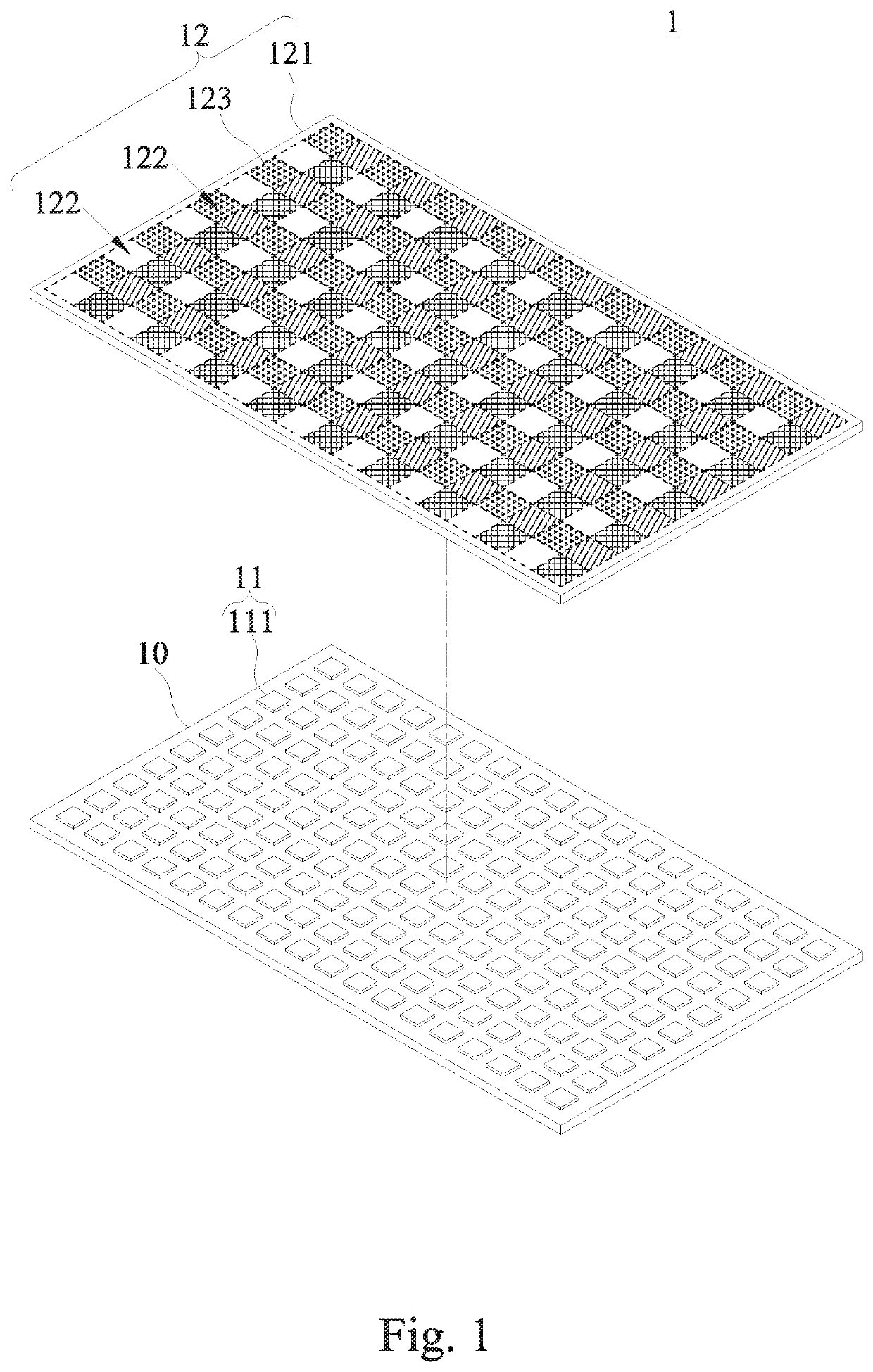

Image

  • LED lighting module and a display having the LED lighting module
  • LED lighting module and a display having the LED lighting module
  • LED lighting module and a display having the LED lighting module

Examples


Embodiment Construction

[0046]To make it easier for our examiner to understand the objective, technical characteristics, structure, innovative features, and performance of the invention, we use preferred embodiments together with the attached drawings for the detailed description of the invention. It is noteworthy that the embodiments are provided for the purpose of illustrating the invention but not intended for limiting the scope of the invention such as the size, proportion, installation gap, etc.

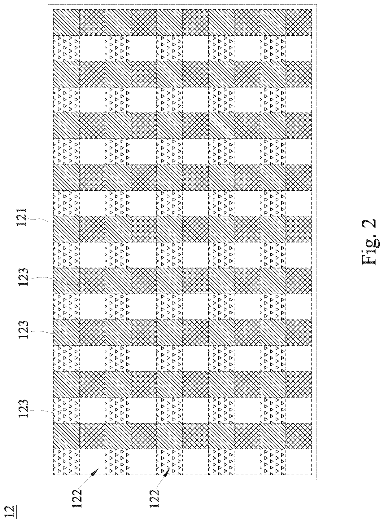
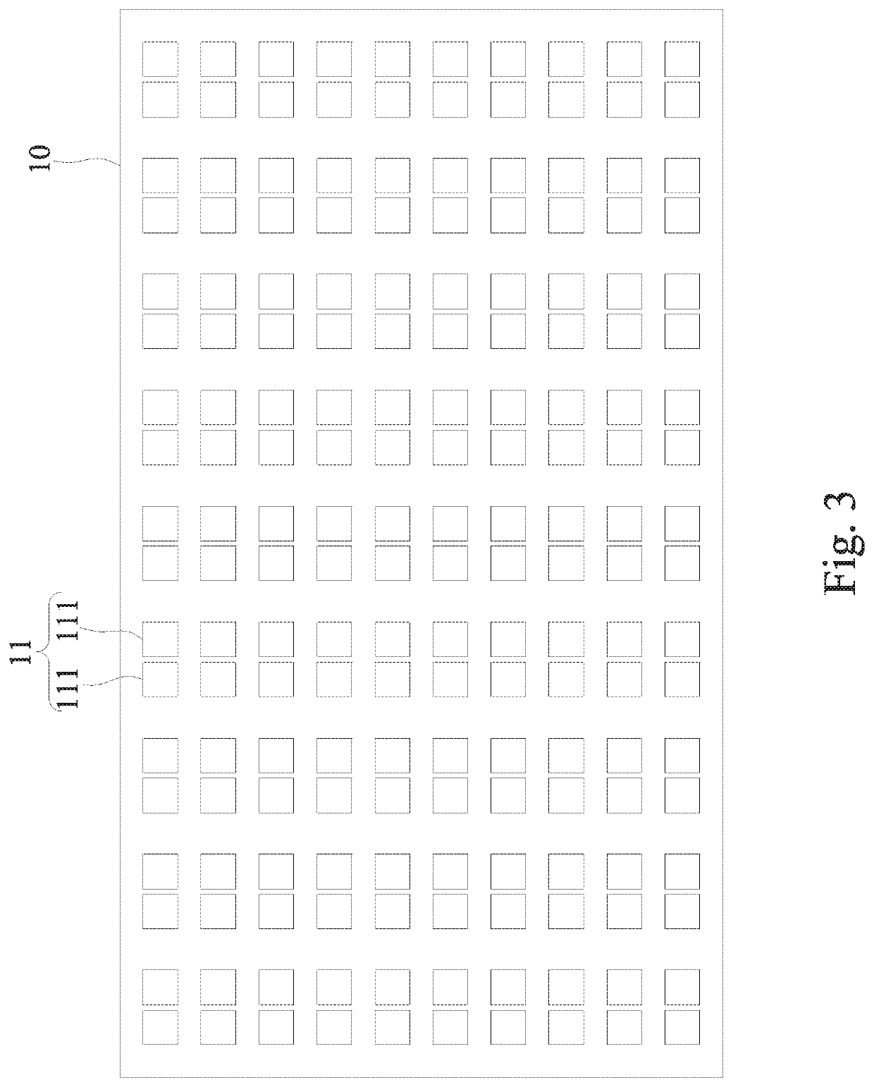
[0047]With reference to FIGS. 1 to 7 for an LED lighting module 1 in accordance with an embodiment of the present invention, the LED lighting module 1 comprises a carrier board 10, a plurality of micro LED arrays 11, and at least one phosphor film 12.

[0048]The micro LED arrays 11 are installed onto the carrier board 10, and the micro LED arrays 11 are formed by at least one micro LED 111. The phosphor film 12 is disposed on a side of the micro LED arrays 11, wherein the phosphor film 12 has a transparent substr...


PUM

PropertyMeasurementUnit
lengthaaaaaaaaaa
transparentaaaaaaaaaa
thicknessaaaaaaaaaa

Abstract

An LED lighting module and a display having the LED module are disclosed. The LED lighting module includes a plurality of micro LED arrays and a phosphor film. The micro LED arrays are respectively composed of at least one micro LED. The phosphor film is disposed on one side of the micro LED arrays; and the phosphor film has a transparent substrate and is provided with a plurality of light emitting regions. The plurality of light emitting regions are arranged adjacent to each other and into a matrix form, and are set corresponding to the micro LED arrays collimation respectively. A part or the whole of the surface of the plurality of light emitting regions is provided with at least one type of phosphor powder.

Description

CROSS-REFERENCE TO RELATED APPLICATIONS[0001]This non-provisional application claims priority under 35 U.S.C. § 119(a) on Patent Application No(s). 107130695 filed in Taiwan, R.O.C. on Aug. 31, 2018, the entire contents of which are hereby incorporated by reference.FIELD OF INVENTION[0002]The present invention relates to the field of LED lighting modules, in particular to the LED lighting module with a micro LED and a phosphor film covering the whole surface of each light emitting region to achieve the effect of outputting different light colors and overcoming the inconvenience of the conventional micro LED capable of outputting a fixed light color only, so as to effectively improve the display performance of the LED lighting module and a display manufactured by applying the LED lighting module.BACKGROUND OF INVENTION1. Description of the Related Art[0003]In the area of the present illumination and display, LED is a popular light source. Since the demand for a design of compact and ...

Claims


Application Information

Patent Timeline
Patent Type & Authority Applications(United States)
IPC IPC(8): F21V9/30
CPCF21Y2113/13F21V9/30F21Y2115/10F21Y2105/10H01L27/156G09F9/33H01L25/0753H01L33/504H01L33/505H01L33/507H01L33/508H01L33/50
Inventor WU, CHING-HUEI
Owner UNITY OPTO TECH CO LTD
Learn More