
Method of detecting rotor blade damage

a technology of rotor blades and rotor blades, which is applied in the direction of machines/engines, instruments, and image enhancement. it can solve the problems of reducing the efficiency of the rotor, damage to the gas turbine blades, and damage to the fan blades

Inactive Publication Date: 2020-02-20
ROLLS ROYCE PLC
View PDF0 Cites 4 Cited by
  • Summary
  • Abstract
  • Description
  • Claims
  • Application Information

AI Technical Summary

Benefits of technology

The patent describes a method for inspecting the blades of a gas turbine engine's rotor using a camera. The camera can capture images of the rotor blades, which may show damage caused by wear and erosion during operation. By analyzing these images, the method can provide valuable information about the condition of the rotor blades, allowing for timely maintenance and repair. The camera can be set to capture images at a high frame rate, making it easier to detect and locate any damage. The method can also allow the pilot of the aircraft to see the rotor blade error, which can improve safety and reliability of the engine.

Problems solved by technology

During operation of a gas turbine engine, it is possible that the gas turbine engine can become damaged due to ingestion of foreign bodies, or from parts of the gas turbine engine that become detached.
Ingestion of foreign bodies, for example birds, or objects in the air at take-off, can damage the gas turbine blades, for example the fan blades.
If one or more of the rotor blades, for example fan blades, becomes damaged, this can cause a reduction in efficiency of the rotor.
The damage to one or more rotor blades, for example fan blades, may also cause undesirable vibration of the rotor due to the imbalance caused by the damage.
However this method requires verification by visual inspection, which may involve endoscopy, on the ground after the flight.
Further the vibrational method is incapable of detecting a situation where one or more rotor blades become damaged but which does not lead to an unbalanced rotor, or to an unbalance which is too small to be detected (for example due to interference from other vibrating parts of the gas turbine engine).
Ground inspections can be time consuming and costly, and require being programmed in advance.
Further the pilot may be unaware of the extent of the damage to the rotor or gas turbine engine and therefore would not know how to respond appropriately, for example to alter the operation of the gas turbine engine, until the ground inspection has been carried out and the cause of the anomaly identified.
Operational loads may cause the blade to twist.
The geometric model may be of a corresponding undamaged rotor blade, and the rotor blade error is the rotor blade damage or deformation.
The rotor blade error may give an indication of the wear and / or erosion experienced by a blade during its operational life.
Advantageously the rotor blade error may be visible to the pilot of the aircraft during flight.
Advantageously the rotor blade error may allow the pilot to ascertain the type of damage experienced by the rotor blade.

Method used


Image

  • Method of detecting rotor blade damage
  • Method of detecting rotor blade damage
  • Method of detecting rotor blade damage

Examples


Embodiment Construction

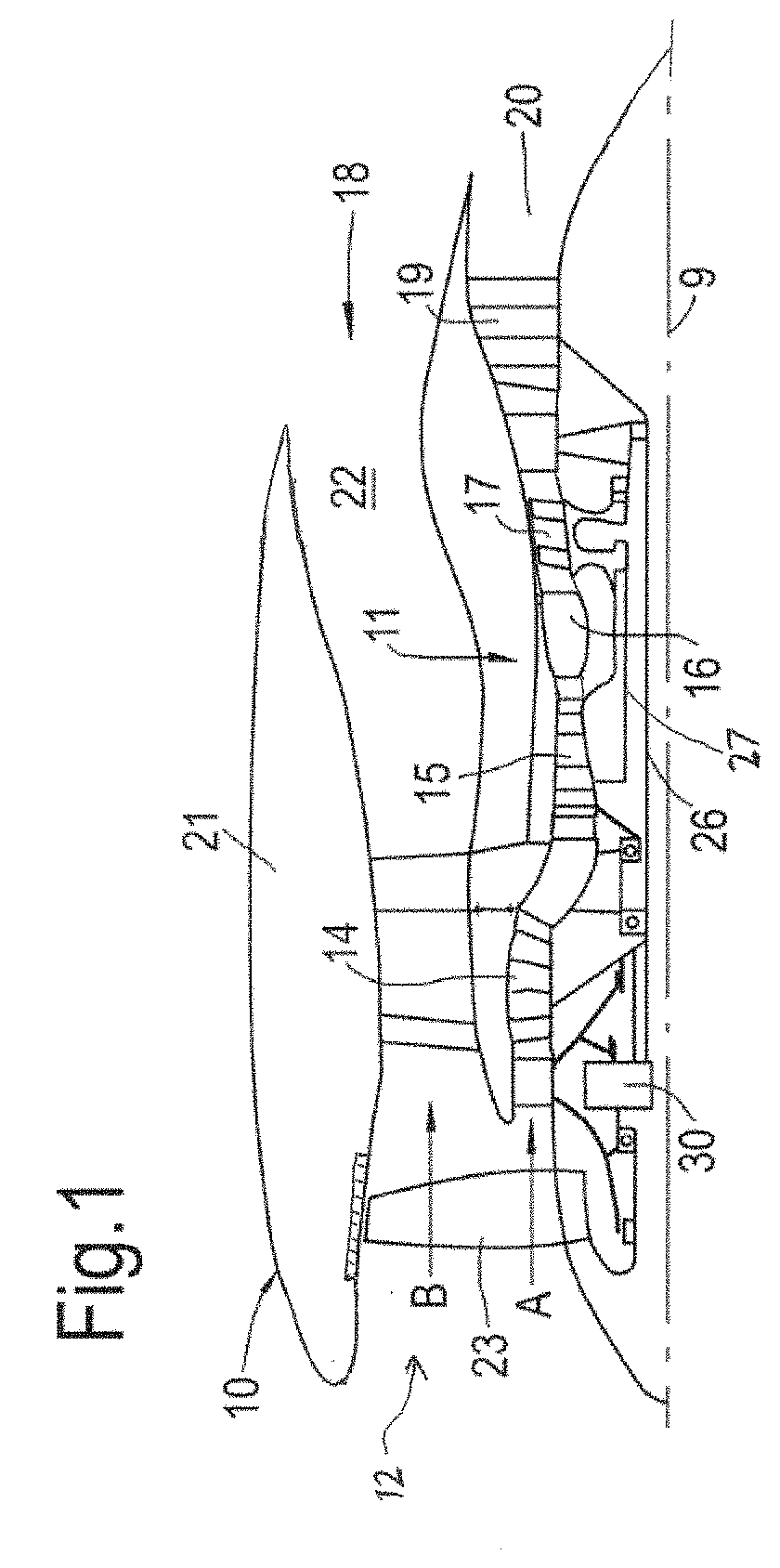
[0050]FIG. 1 illustrates a gas turbine engine 10 having a principal rotational axis 9. The engine 10 comprises an air intake 12 and a propulsive fan 23 that generates two airflows: a core airflow A and a bypass airflow B. The gas turbine engine 10 comprises a core 11 that receives the core airflow A. The engine core 11 comprises, in axial flow series, a low pressure compressor 14, a high-pressure compressor 15, combustion equipment 16, a high-pressure turbine 17, a low pressure turbine 19 and a core exhaust nozzle 20. A nacelle 21 surrounds the gas turbine engine 10 and defines a bypass duct 22 and a bypass exhaust nozzle 18. The bypass airflow B flows through the bypass duct 22. The fan 23 is attached to and driven by the low pressure turbine 19 via a shaft 26 and an epicyclic gearbox 30.

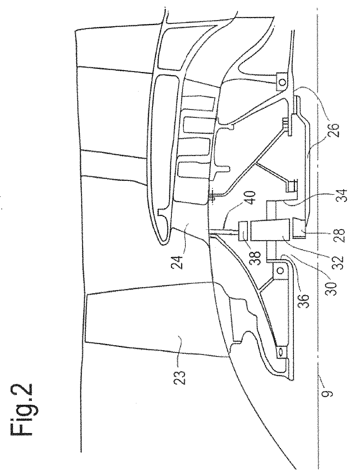
[0051]An exemplary arrangement for a geared fan gas turbine engine 10 is shown in FIG. 2. The low pressure turbine 19 (see FIG. 1) drives the shaft 26, which is coupled to a sun wheel, or sun gear,...


PUM


Abstract

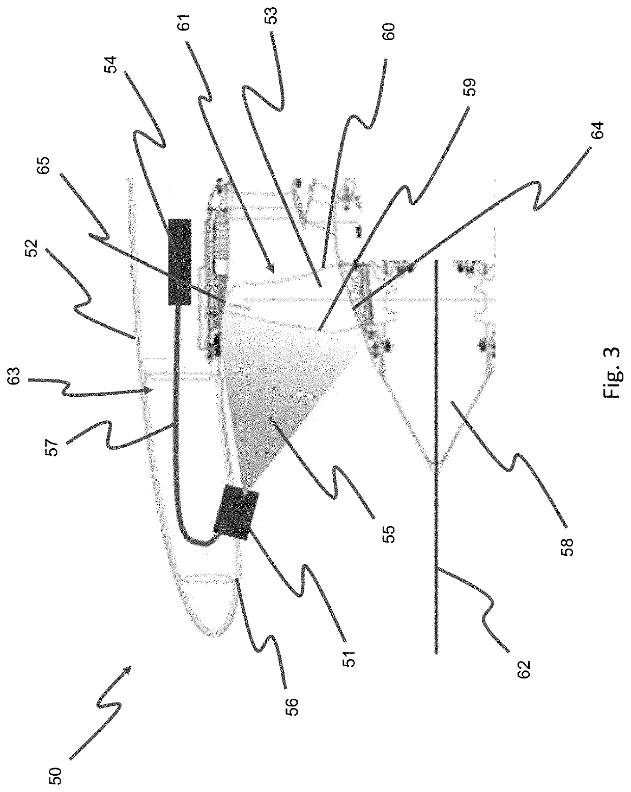
A method of detecting rotor blade damage on a gas turbine engine is provided comprising the steps of taking an image of a rotor blade, processing the image to produce a blade profile using an edge detection algorithm and determining a rotor blade error by comparing the blade profile with a geometric model of a corresponding blade.

Description

CROSS-REFERENCE TO RELATED APPLICATIONS[0001]This application is based upon and claims the benefit of priority from British Patent Application Number 1813432.0, filed 17 Aug. 2018, the entire contents of which are incorporated by reference.BACKGROUNDTechnical Field[0002]The present disclosure concerns a method for detecting rotor blade damage, a gas turbine engine, a geared turbofan, an aircraft and an apparatus of detecting rotor blade damage.Description of the Related Art[0003]During operation of a gas turbine engine, it is possible that the gas turbine engine can become damaged due to ingestion of foreign bodies, or from parts of the gas turbine engine that become detached. Ingestion of foreign bodies, for example birds, or objects in the air at take-off, can damage the gas turbine blades, for example the fan blades. Damage from foreign bodies is referred to as foreign objection damage (FOD). Damage from parts of the gas turbine engine that have become detached is referred to as ...

Claims


Application Information

Patent Timeline
IPC IPC(8): F01D21/00G06T7/00G06T7/13
CPCB64D2045/0085G06T7/13F01D21/003G06T7/001G06T2207/30164F05D2260/80F05D2270/11F05D2270/8041F05D2260/83F05D2270/708
Inventor EASTMENT, BENJAMIN J.
Owner ROLLS ROYCE PLC
Learn More