
Fiber configurations for wellbore treatment compositions

a fiber configuration and composition technology, applied in the direction of fluid removal, borehole/well accessories, chemistry apparatus and processes, etc., can solve the problems of gas slowing or even stopping, passages tend to close, and non-uniform delivery of proppant through the wellbor

Active Publication Date: 2020-02-06
EASTMAN CHEM CO
View PDF1 Cites 31 Cited by
  • Summary
  • Abstract
  • Description
  • Claims
  • Application Information

AI Technical Summary

Benefits of technology

The use of fibers in fracturing fluids reduces viscosity, which leads to less residual viscosifier left behind in fractures. This residue can interfere with the flow of oil or gas out of the fissure.

Problems solved by technology

However, these passages tend to close when the pumping pressure eases and flow of oil or gas slows or even stops.
This leads to a non-uniform delivery of proppant through the wellbore with ultimate plugging of the wellbore.
However, there are limits to how high the viscosity of a fracturing fluid can be.
One limitation of such viscous fluids is simply the physical handling / pumping of such fluids since larger motors are needed to deliver the thick heterogeneous suspensions.
It is also known that use of fracturing fluids with very high viscosities can lead to fractures with widths larger than desired, which may result in formations in non-producing rock formations or into water.
In either case, the well productivity becomes compromised.
However, the requirement of minimal proppant settling while still controlling the fracture geometry often leads to a number of undesirable trade-offs.
This residual viscosifier can interfere with the flow of oil or gas out of the fissure.
While use of fibers can be advantageous for reducing the viscosity of the fracture fluid and for suitable proppant delivery to fissures, one disadvantage of their use is that the fibers can be left behind and trapped in the fissures, which can lead to reduced flow of oil and gas to the well.
The problem with these degradable polymers is that they tend to decompose at temperatures approaching 100° C., and as such, their utility becomes limited.
Typical wellbore temperatures can range from 100 to 200° C. and so stability and utility of such fibers are limited.
Furthermore, certain degradable fibers may leave residues that tend to precipitate salts in the presence of the excessive amounts of calcium or magnesium in connate water.

Method used


Image

  • Fiber configurations for wellbore treatment compositions
  • Fiber configurations for wellbore treatment compositions
  • Fiber configurations for wellbore treatment compositions

Examples


example 1

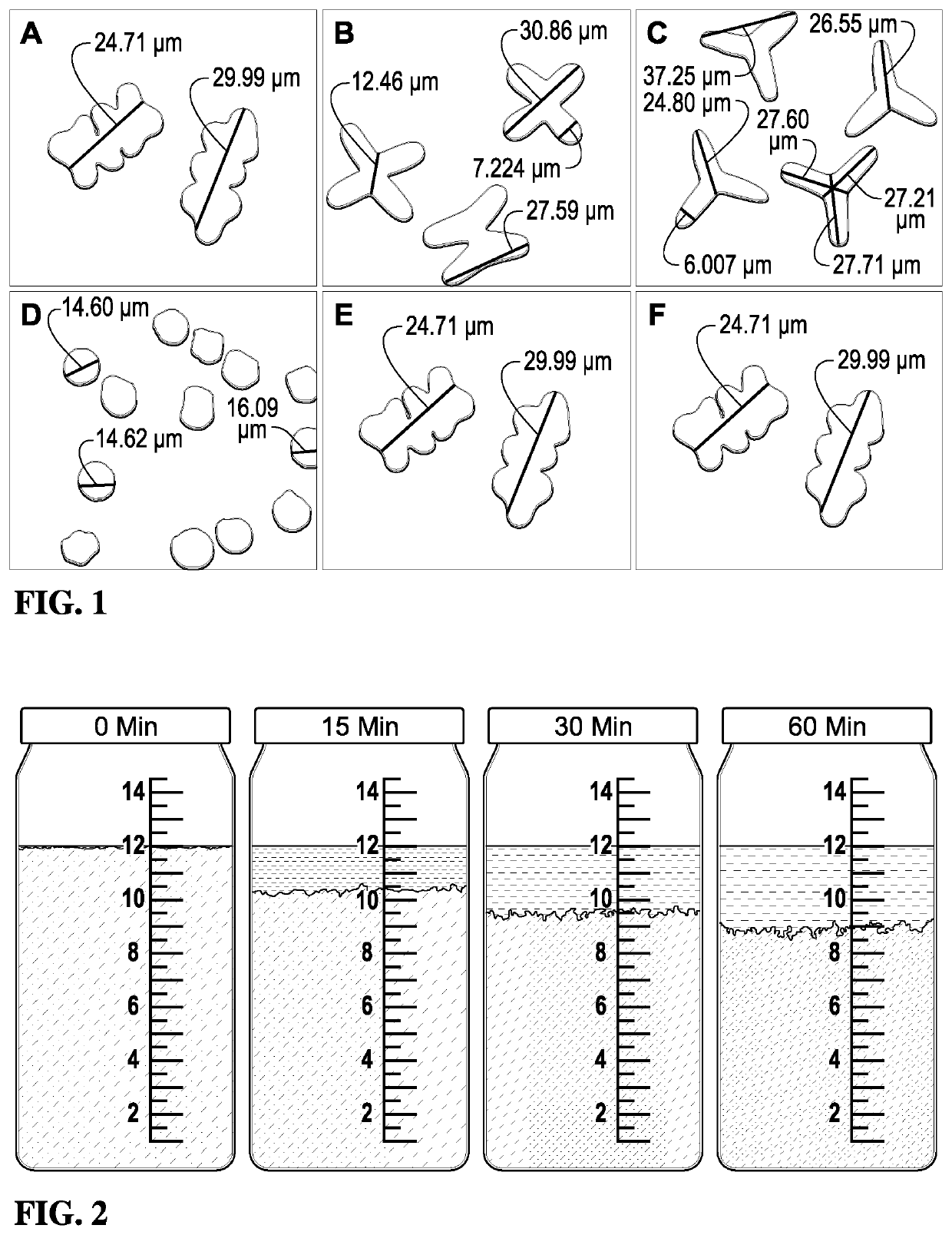
[0085]Cellulose acetate-based fibers were produced from Eastman cellulose acetate (CA-394-60S) polymer with a dry spinning process using acetone as a solvent. To probe the effect of fiber morphological properties on proppant settling performance, three fiber variables were selected: fiber length, fiber cross-sectional geometry, and fiber form (e.g., straight or crimped). The crimping process served to emboss a crimping structure onto each filament. In order to study the effect of fiber cross-sectional geometry, four different geometries were tested including octagonal, X-shaped, trilobal, and round. Microscopy images and the approximate dimensions of the different fiber geometries are depicted in FIG. 1 at 1000-2000× magnification. As shown in FIG. 1, (A) is the cellulose acetate octagonal (“popcorn”), (B) is the cellulose acetate “X-shape,” (C) is the cellulose acetate “trilobal,” (D) is the poly-lactic acid “round,” (E) is the straight fibers, and (F) is the crimped fibers.

[0086]A...


PUM

PropertyMeasurementUnit
temperaturesaaaaaaaaaa
average angleaaaaaaaaaa

Abstract

Suspension of proppants in hydraulic fracturing applications can be strongly affected by the cross-sectional shapes and lengths of the fibers present in the wellbore treatment compositions. For instance, it has been observed that crimped cellulose ester fibers with a trilobal cross-section and an optimized length can provide enhanced suspension of proppants in aqueous fracturing fluids. Furthermore, the present invention demonstrates that non-round cellulose ester fibers can provide superior proppant suspension properties relative to polylactic acid fibers with a round cross-section.

Description

RELATED APPLICATIONS[0001]This application claims the benefit of U.S. Provisional Patent Application Ser. No. 62 / 406,757 filed Oct. 11, 2016, the entire disclosure of which is incorporated herein by reference.BACKGROUND1. Field of the Invention[0002]The present invention generally relates to wellbore treatment compositions. More particularly, the present invention generally concerns the use of specific types of fibers in wellbore treatment compositions.2. Description of the Related Art[0003]Hydraulic fracturing is a process for enhancing the output of oil or gas wells by forcing fluid (>95% water) into an existing wellbore under high pressure so as to cause fractures or fissures to occur in the surrounding shale or tight-rock formations. Typically, a hole is drilled vertically, often at least a mile down, and then it gradually is oriented to a horizontal position that extends for several more thousand feet. After the well is drilled, casement placed and cemented in place, small p...

Claims


Application Information

Patent Timeline
Patent Type & Authority Applications(United States)
IPC IPC(8): C09K8/90C09K8/80C09K8/92
CPCC09K8/80C09K8/92C09K8/90C09K2208/08C09K8/035C09K8/665C09K8/70E21B43/267
Inventor COLLINS, NICK ALLENISLAM, S M BEDARULCOOK, PHILLIP MICHAELGHOSH, KOUSHIK
Owner EASTMAN CHEM CO
Learn More