
Linear accelerator system for stable pulsing at multiple dose levels

a linear accelerator and stable technology, applied in the field of xray devices, can solve problems such as affecting the performance of the system, presenting challenges to the linac system, and it is impractical to take a first scan of a container

Active Publication Date: 2020-01-09
ETM ELECTROMATIC INC
View PDF0 Cites 2 Cited by
  • Summary
  • Abstract
  • Description
  • Claims
  • Application Information

AI Technical Summary

Benefits of technology

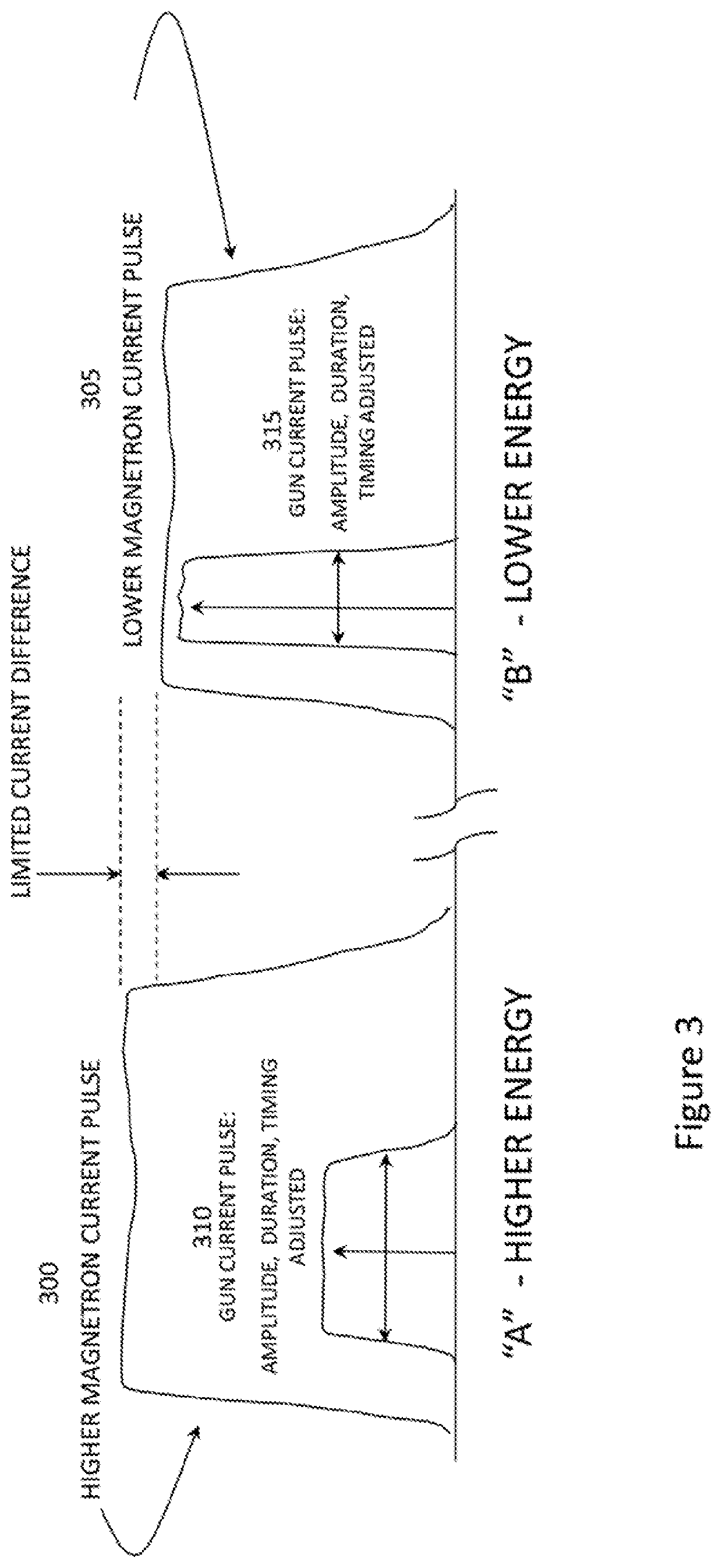
This patent describes a new way to create a stable sequence of pulses with different energies. It also provides precise control over the dosage of each pulse. The invention uses a single energy pulse but with higher and lower dose modes, and a single grid gun driver to simplify design. To prevent cooling issues, the invention adjusts the frequency of the RF power generator during periods when the scanning function is disabled and compensates for changes in ambient temperature. This ensures that the dose of the first pulse after re-enabling is within 10% of the average dose during the period when scanning is enabled.

Problems solved by technology

In addition, the Q of the linac can affect the performance of the system.
However, it is impractical to take a first scan of a container resting on the bed of a truck at a first X-ray energy, and then take a second, later scan of that same container at a second X-ray energy.
This interleaving, however, can present challenges to a linac system since the performance of a linac with its resonant structure is highly dependent on a good frequency match.
These techniques have been sufficient when the time between energy changes is long, such as seconds or many seconds, but have been less effective when the time between energy changes is a fraction of a second.
However, detuning can cause instabilities in performance, and is difficult to do in a fraction of a second if a mechanically-tuned magnetron is the RF source.
A challenge with applying prior art techniques for changing linac energy on a rapid time scale in an ABABABAB fashion can be the undesired corresponding detuning of the RF source.
For example, in addition to intentional tuning, reducing or increasing RF power from a magnetron typically results in a change in frequency of the RF output.
If the frequency change is large enough, the linac's resonance is no longer matched to the frequency of the RF excitation pulse, and the system fails to operate.
Because of the sensitivity of linac-based systems to changes in frequency, the prior art has generally not been able to provide a fully optimized train of stable, interleaved pulses of different energies such as an ABABABABAB (etc.) pattern, especially where the energy must be changed rapidly, from one pulse to the next, at a 2.5-millisecond basis or shorter such as required for a pulse rate of 400 or more pulses per second, and especially when that rapid change is done with a magnetron driven system
This limits the ability to rapidly switch a magnetron system between higher and lower energy levels while still maintaining a frequency match with the linac, because the magnetron frequency will shift upon a power change and a mechanical tuner simply cannot be moved rapidly enough to support a 2.5 millisecond or shorter period between pulses.
One drawback of a magnetron is that its mode and stability can become unfavorable if the magnetron is operated at a peak power too much different from its optimum or maximum peak power.
However, as noted before, changing the power output of the magnetron also causes a change to the output frequency of the RF pulse, such that the output frequency of the magnetron can be a mismatch for the linac.
Changing this current by many amperes may cause a significant detuning with respect to the resonance of a given linac.
While AFC circuits can compensate for long term changes in frequency, such circuits are not intended to compensate for instantaneous pulse-to-pulse changes such as occur with a magnetron is driven with an alternating sequence that varies by several amps.
As a result, such approaches can result in instability of the magnetron-linac system, and there has been a need for a system and technique for maintains stability while permitting the use of interleaved pulses of different RF powers to generate an interleaved pattern of X-ray pulses of different energies.
In addition to the challenges to prior art systems that result from variations in RF matching between the output frequency of a magnetron and the resonant frequency of the linac, the prior art has also had challenges in maintaining a consistent dose from pulse to pulse when interleaved pulses of different energies are generated.
However, for the use of X-rays to differentiate among materials, as required for cargo scanning applications, such changes in dose per pulse are undesirable.
While dose control in medical applications can be achieved through changes in repetition rate, this is not desirable for cargo scanning applications which depend upon having consistent repetition rates.
A further problem in cargo scanning applications is the intermittent nature of the operation of such scanning systems.
While this affects only the first few pulses, or 10 pulses or more after scanning is re-initiated, before the AFC circuit can achieve a good match, this lack of consistency in output energy and / or dose can affect the quality of the resulting images, and is therefore undesirable.
These warm-up approaches have the significant disadvantage of potentially generating some amount of X-rays even when the electron gun is not being pulsed.
Another disadvantage is the consumption of average power that is not used for the generation of X-rays.
These approaches are inefficient and therefore undesirable.

Method used


Image

  • Linear accelerator system for stable pulsing at multiple dose levels
  • Linear accelerator system for stable pulsing at multiple dose levels
  • Linear accelerator system for stable pulsing at multiple dose levels

Examples


Embodiment Construction

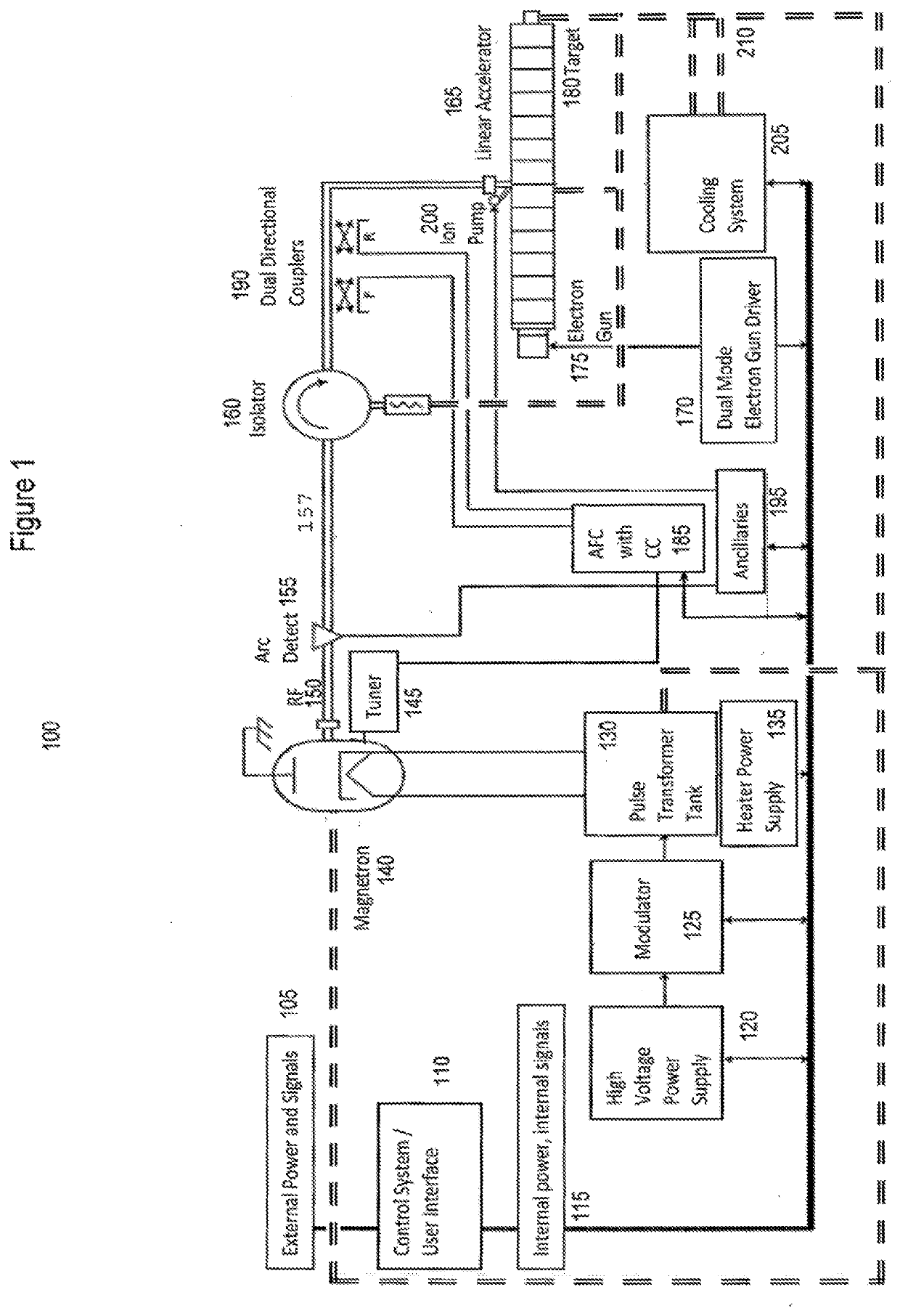
[0042]Referring first to FIG. 1, an X-ray scanning system according to an embodiment of the invention is shown in block diagram form at 100. In such an embodiment, external power and signals 105 are received by a control processor 110. Included among the external signals are, typically, one or more trigger signals indicating that the user desires to scan an object, for example a cargo container on a vehicle passing before the scanning system. The control processor 110 controls, directly or indirectly, the operation of the remaining functional blocks shown in FIG. 1 by virtue of signals sent on internal bus 115, which, for simplicity, is shown combined with internal power.

[0043]In response to the trigger signal(s), the control processor 110 sends, depending upon the implementation, a plurality of signals to initiate generation of an X-ray pulse. In particular, the processor 105 sends control signals to a high voltage power supply 120 and an associated modulator 125 which receives the...


PUM


Abstract

A linac-based X-ray system for cargo scanning and imaging applications uses linac design, RF power control, beam current control, and beam current pulse duration control to provide stable sequences of pulses having different energy levels or different dose.

Description

RELATED APPLICATION[0001]This application is related to and claims the benefit of U.S. patent application Ser. No. 14 / 192,864, filed on Feb. 27, 2014, now U.S. Pat. No. 9,622,333, and also is related to and claims the benefit of U.S. patent application Ser. No. 14 / 634,361, filed Feb. 27, 2015, now U.S. Pat. No. ______, both of which are incorporated herein by reference for all purposes.FIELD OF THE INVENTION[0002]The present invention relates generally to X-ray devices, and more particularly relates to linac-based scanning systems and methods able to generate pulses of different energies and doses.BACKGROUND OF THE INVENTION[0003]Linear accelerator (“linac” hereinafter) X-ray generating systems have been in use in the medical environment for a number of years. More recently, such systems have begun to be used in the industrial environment, particular for cargo scanning. To distinguish the materials inside a cargo container, X-ray pulses of different energies have been used. Energies...

Claims


Application Information

Patent Timeline
Patent Type & Authority Applications(United States)
IPC IPC(8): H05H7/02G01V5/00H05H9/04
CPCH05H2007/022H05H7/02H05H9/048G01V5/0016G01V5/22
Inventor NIGHAN, JR., WILLIAM L.KORRINGA, MAARTENROLIN, JOHN HOWARDHENDERLONG, DEVIN KIRK
Owner ETM ELECTROMATIC INC
Learn More