Milling tool

a technology of milling tool and tool body, which is applied in the field of milling tool, can solve the problems of very low surface friction resistance, and achieve the effects of reducing friction resistance, reducing friction resistance, and reducing friction resistan

Inactive Publication Date: 2020-01-02
HPTEC
View PDF0 Cites 1 Cited by
  • Summary
  • Abstract
  • Description
  • Claims
  • Application Information

AI Technical Summary

Benefits of technology

[0007]Accordingly, the milling tool according to the present invention is distinguished by the fact that the main feature has a smooth lateral surface arranged on the side facing away from the main cutter in the direction of rotation. Surprisingly, it has been found that not only can such a tool according to the present invention be manufactured cost-effectively, because no additional elevations and recesses have to be worked into the lateral surface, but this tool also has very good strength and stability. Even when the milling tool has penetrated a comparatively long way into the material of the workpiece, the smooth surface affords very low frictional resistance, to the extent that the main body comes into contact with the workpiece at all. On account of these properties, the milling tool according to the present invention is usable in principle also for a wide variety of technical areas of application, including for instance the machining of:
[0024]It has already been stated that exemplary embodiments of the present invention are suitable for different areas of application. As a rule, the milling tool is manufactured, for example, from solid carbide. Advantageously, the milling tool can, in one exemplary embodiment, have a coating, for example, a carbon coating, for example, with diamond. In this way, the chip formation can be improved and the stability of the tool increased.

Problems solved by technology

Even when the milling tool has penetrated a comparatively long way into the material of the workpiece, the smooth surface affords very low frictional resistance, to the extent that the main body comes into contact with the workpiece at all.

Method used


Image

  • Milling tool

Examples


Embodiment Construction

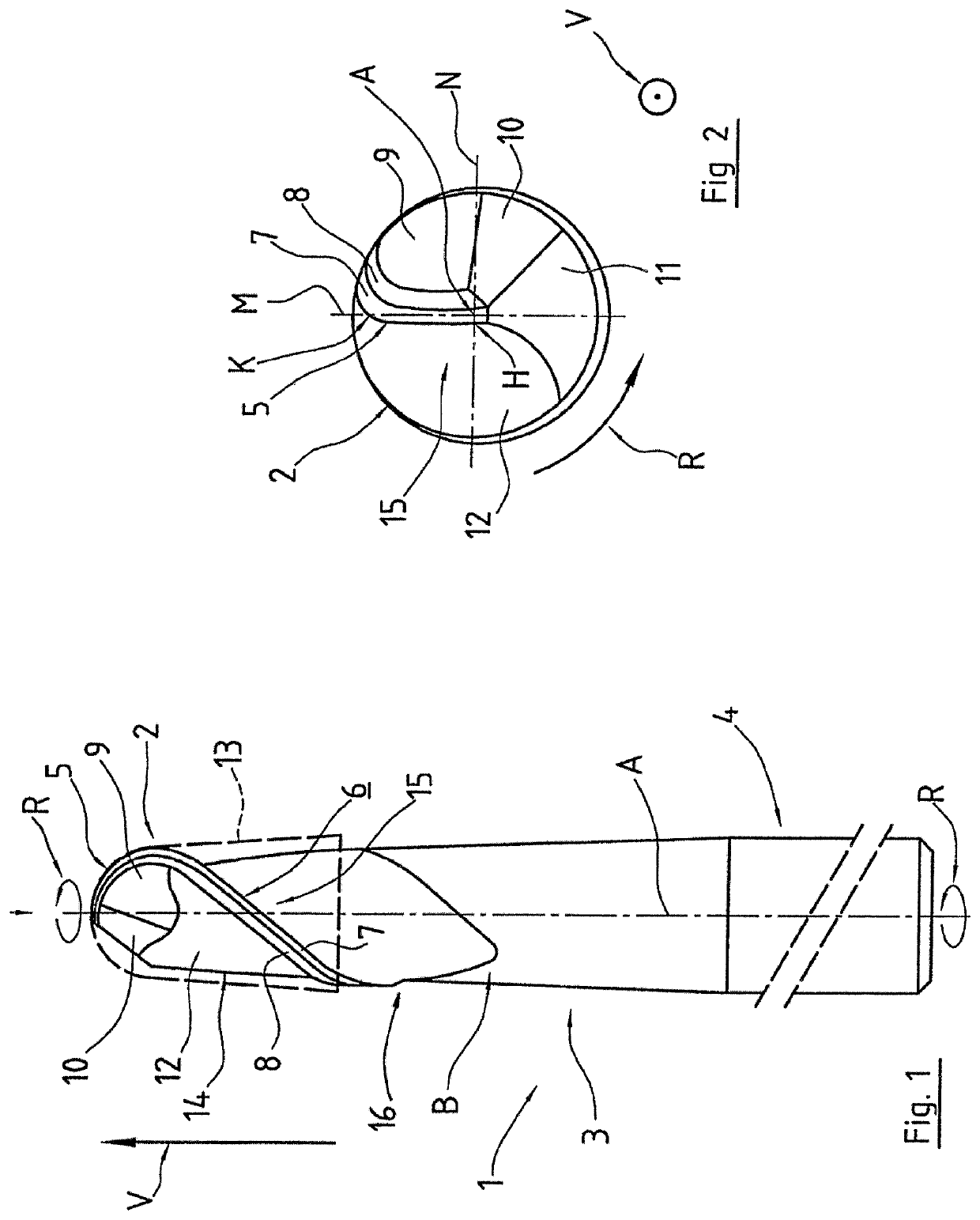
[0028]FIG. 1 shows a milling tool 1 having a milling head 2, a main body 3, and a cylindrical portion as shank 4. Located on the milling head 2 is a radius cutter 5, which transitions into a main cutter 6 of the main feature in the region of the main body 3. Both the radius cutter 5 and the main cutter 6 are accompanied by in each case two flanks 7, 8, which extend parallel to the respective cutters 5, 6. Furthermore, arranged behind the radius cutter 5 in the direction of rotation R are three chip spaces 9, 10, 11, the surfaces of which are in part planar or curved away from the axis of rotation A. Thus, when the milling tool 1 is in contact with a workpiece in the region of the milling head 2, it exhibits less friction in the region adjoining the radius cutter 5.

[0029]Located behind the radius cutter 5 and the flanks 7, 8 in the direction of rotation R is the lateral surface 12, which is formed in a smooth manner. The lateral surface 12 is set back behind the cutters 5, 6 in its d...


PUM


Abstract

A milling tool for milling and / or drilling workpieces, which is rotatable in a direction of rotation about an axis of rotation during machining, comprising a milling head, which has a radius cutter that describes a portion in the form of a circular arc such that the milling head takes up a partially spherical, in particular a hemispherical volume, in rotation, a main body, which has a main feature in the form of a helical recess with respect to the rotation volume taken up by the rotating milling tool in order to form a conveying helix, wherein the main feature is provided with a cutting edge as main cutter, wherein the main feature has a smooth lateral surface arranged on the side facing away from the main cutter in the direction of rotation.

Description

CROSS REFERENCE TO RELATED APPLICATIONS[0001]This application is a continuation of International Application No. PCT / EP2018 / 055672 filed Mar. 7, 2018, which designated the United States, and claims the benefit under 35 USC § 119(a)-(d) of German Application No. 20 2017 101 382.0 filed Mar. 10, 2017, the entireties of which are incorporated herein by reference.FIELD OF THE INVENTION[0002]The present invention relates to a milling tool for milling workpieces.BACKGROUND OF THE INVENTION[0003]Various milling tools are known from the prior art, which make it possible among other things to machine specific materials, for example, to machine plastic, for example, for use in conjunction with the production of dental blanks or the like. In order to make a sufficiently large material cross section available, in some of these tools, the lateral surface of the main body is formed in a ribbed manner in the region of the main feature, or in the region that is located behind the main cutter in the...

Claims


Application Information

Patent Timeline
Patent Type & Authority Applications(United States)
IPC IPC(8): B23C5/10
CPCB23C5/1009B23C2210/201B23C2210/241B23C2210/04B23C2210/44
Inventor NETZER, STEFAN
Owner HPTEC
Why Eureka
Try Eureka