Drilling tool

Inactive Publication Date: 2020-01-02
HPTEC
View PDF0 Cites 0 Cited by
  • Summary
  • Abstract
  • Description
  • Claims
  • Application Information

AI Technical Summary

Benefits of technology

The present invention relates to a drilling tool with a constant core cross-sectional area during grinding. This means that the tool tip can be maintained at the drilling point without any geometric changes. The size and geometry of the conveying helix and cutting edges can be maintained. Compared to conventional drilling tools, the regrinding operations can be performed more frequently. The cross-sectional area of the core is maintained even after the first regrinding, which helps to maintain the performance of the drilling tool. The drilling tool has at least one cutting edge, specifically in the region of the tool tip. The cross-sectional area of the core may increase or decrease in specific regions, depending on the direction of advance. This results in a more stable drilling tool, as material is progressively forced out of the tool.

Problems solved by technology

Because of this, in the case of continuous use it also becomes ever more difficult for the drill, having a blunted tip, to be positioned in a centered manner, i.e. the precision of the tool is progressively lost.
In particular, however, such small drills, for instance from the manufacturing of printed circuit boards, can normally only be reground once or twice and then, upon further blunting of the tool tip, they have a reduced performance.
As the tool tip of the drill becomes increasingly blunted in operation, it must be reground after a certain period of time.
Upon repeated grinding, however, this change becomes ever greater, such that the performance of the drilling tool generally decreases at the latest after the second grinding in that, for example, the breakage rate increases, the surface quality of the drilling wall decreases, there is increased deflection of the tools in relation to the center, there is increased burr formation upon entry and exit, or the like.
Piece by piece, however, the depth of the conveying helix thus lessens progressively, such that, on the one hand, the stability of the drilling tool increases progressively toward the location at which the drilling tool is clamped, and the material removed from the workpiece is progressively forced out of the drilling tool.
The closer one is to the tool tip, the more rapidly must transport of material be effected, because the machined-off chips and the machined-off drilling dust tend to interfere with the machining when material is being removed there from the workpiece.

Method used


Image

  • Drilling tool
  • Drilling tool

Examples


Embodiment Construction

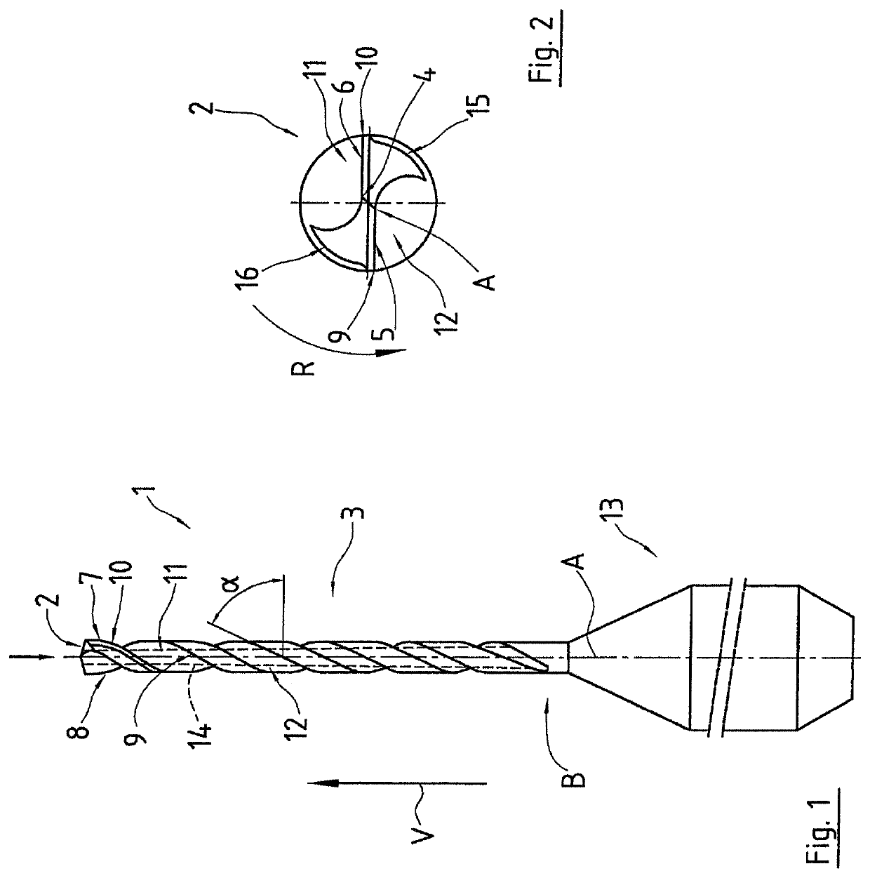
[0024]FIG. 1 shows a drill 1 having a tool tip 2 and a basic body 3. The drill 1 is rotated about an axis of rotation A for the purpose of drilling a workpiece. In a rotation about the axis of rotation A, the basic body 3 occupies a cylindrical volume.

[0025]The tool tip 2 is shown in a top view in FIG. 2. Going through the axis of rotation A is a chisel edge 4, which in turn merges into two main cutting edges 5, 6 of the tool tip 2. These main cutting edges 5, 6 extend outward, and then merge into the main groove 7, 8, or into the secondary cutting edges 9, 10. In the intermediate region of the main groove there are thus formed two helical depressions 11, 12, which serve as conveying helices and provide for transport of the machined-off drilling dust, or the machined-off chips, contrary to the direction of advance V. The conveying helices 11, 12 each end in the region of the point B. Up to this point, or up to this height, the depth of each also decreases. Additionally indicated, by...


PUM


Abstract

Proposed is a drilling tool for drilling workpieces, having a tool tip and a basic body and a core, wherein the basic body has at least one main groove as at least one helical depression, for the purpose of realizing a conveying helix in each case. For the purpose of prolonging the service life, the core, in a first portion that starts at the tool tip and / or extends to the tool tip, has a constant cross-sectional area perpendicular to the axis of rotation and, in an adjoining second portion, counter to the direction of advance, has a cross-sectional area that increases, at least in portions.

Description

CROSS REFERENCE TO RELATED APPLICATIONS[0001]This application is a continuation of International Application No. PCT / EP2018 / 055586 filed Mar. 7, 2018, which designated the United States, and claims the benefit under 35 USC § 119(a)-(d) of German Application No. 10 2017 105 171.6 filed Mar. 10, 2017, the entireties of which are incorporated herein by reference.FIELD OF THE INVENTION[0002]The present invention relates to a drilling tool for drilling workpieces.BACKGROUND OF THE INVENTION[0003]According to the prior art, drilling tools are usually reground after a certain period of time in operation; this also applies to comparatively small drills that are used, for example, in the manufacture of printed circuit boards (PCB). This operation is necessary because, during use, the tip of the drilling tool becomes ever more blunted as a result of the stress resulting from friction and impacts. Because of this, in the case of continuous use it also becomes ever more difficult for the drill,...

Claims


Application Information

Patent Timeline
IPC IPC(8): B23B51/02
CPCB23B2251/408B23B2251/426B23B2251/046B23B51/02B23B2251/18B23B2251/404B23B51/011
Inventor NETZER, STEFAN
Owner HPTEC
Why Eureka
Try Eureka