Heat Exchange System and Method

a heat exchange system and heat exchange technology, applied in the field of heat exchange systems, can solve the problems of limited heat exchanger size, substantial temperature change in the output of warmed fluid, and many challenges faced by heat exchange system designers, and achieve the effects of reducing the output temperature, increasing the efficiency of the heat exchanger, and stable output temperatur

Active Publication Date: 2019-10-10
ADVANCED STEAM TECH
View PDF0 Cites 0 Cited by
  • Summary
  • Abstract
  • Description
  • Claims
  • Application Information

AI Technical Summary

Benefits of technology

The patent is for a heat exchange system that produces a steady output temperature for a heated fluid while minimizing the temperature of a cooled fluid. The system uses a tank with two sections: one section for the warm fluid and another for the cooler fluid. A re-circulating loop connects directly to the middle of the tank, which keeps the warm fluid at a stable temperature. The cooler fluid flows through a separate section of the tank, extracting extra heat energy before leaving the tank. The system can be designed with no barrier between the warm and cooler fluid sections or a separator to prevent mixing between them. The tank structure includes vertical thermally-conductive pipes and horizontal plates to facilitate the heat exchange process. The technical effect of this patent is a more efficient heat exchange process that produces a stable output temperature for the warm fluid while minimizing energy waste.

Problems solved by technology

Designers of heat exchange systems have faced many challenges such as limitations on the size of the heat exchanger.
Managing the temperature of the cooled fluid leaving the system is also a challenge facing heat exchange systems due to efficiency and regulatory concerns.
Changes in the demand for heating require that heat exchange systems be able to provide vastly different amounts of heating, which can lead to substantial temperature changes in the output of the warmed fluid.
Although this approach may reduce the variability of the warmed fluid output temperature, the cooled fluid temperature leaving the heat exchanger can vary drastically.
As a result of the variable flow rate through the heat exchanger, the quantity of energy transmitted cannot be precisely controlled causing the temperature of the output water to vary.
Additionally, the high temperature of the steam limits control, but is needed for high usage situations.
A varying output temperature of the cooled fluid from the heat exchanger can reduce the efficiency of the energy exchange since energy remaining in the cooled fluid is often wasted.
In addition to being inefficient, dumped fluids often must be below a specified temperature to avoid damaging sewer systems or to avoid causing thermal pollution that can lead to problems such as algae blooms.
Many times a facility is built up around these failing units and replacing them with a similarly sized unit would entail major demolition.
. . for partly pre-heating the first fluid before it is heated by the second fluid, whereby the first fluid temperature at the first fluid circuit downstream end will be stabilized.” Although the Lach patent attempts to improve the temperature stability of a first fluid leaving the heat exchanger, the Lach patent fails to provide a mechanism for stabilizing and reducing the output temperature of the cooled fluid.
While it is possible to obtain temperature control of the warmed fluid in semi-instantaneous water heaters, the output temperature of the cooled fluid is uncontrolled.
Although designs by Lach and Clark have attempted to solve some of the problems associated with heat exchangers, all of these problems have yet to be fully addressed.

Method used


Image

  • Heat Exchange System and Method
  • Heat Exchange System and Method
  • Heat Exchange System and Method

Examples


Embodiment Construction

[0035]The present invention may be used with any type of heat exchanger and is particularly suited for use with domestic hot water systems, ammonia based refrigeration systems, heating water / glycol building heat systems, oil or heat transfer fluid systems, wash stations, and emergency showers. However, for descriptive purposes, the present invention will be described in use with a heat exchanger heating water with hot steam.

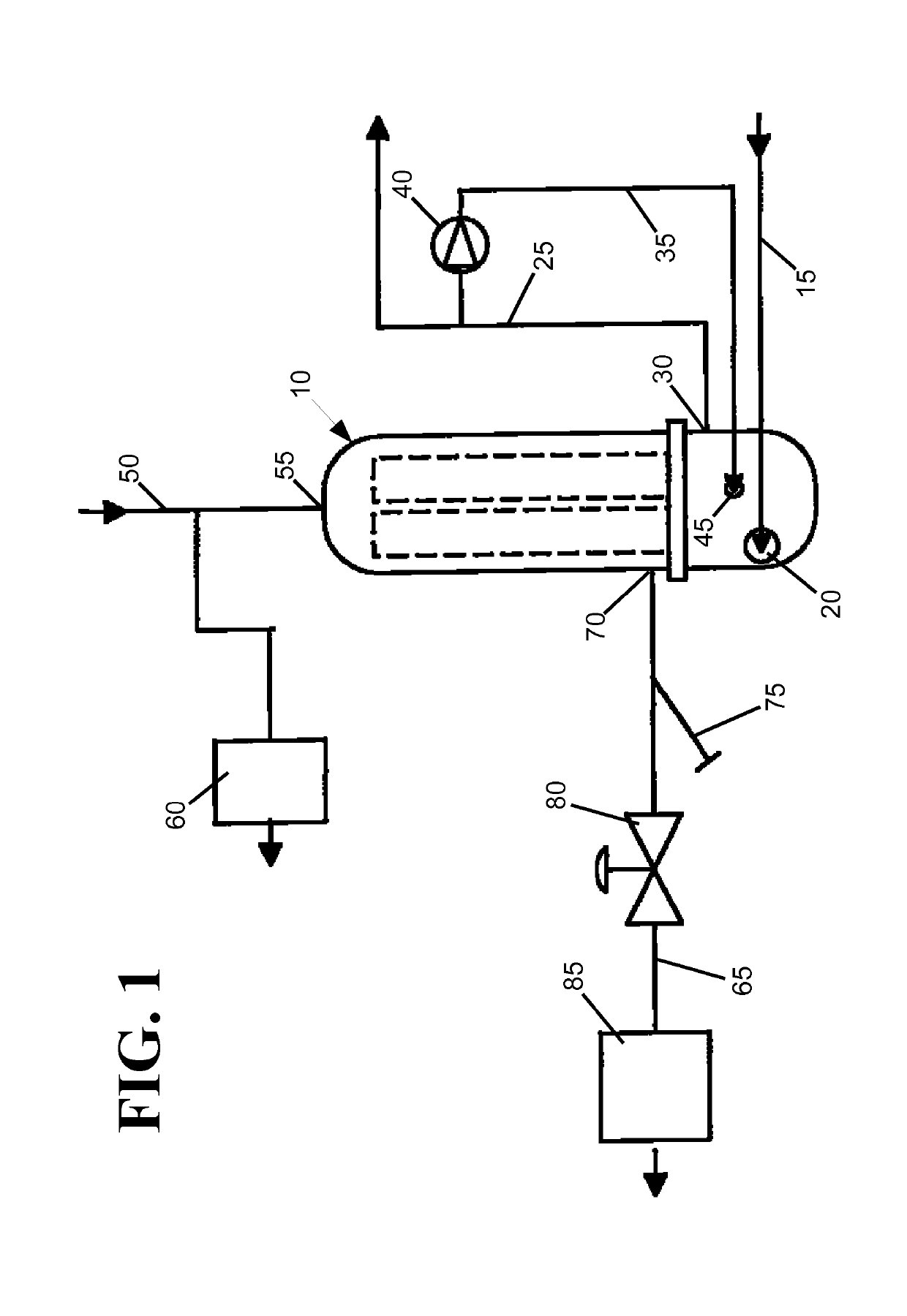
[0036]FIG. 1 shows a circuit diagram of a heat exchange system with a heat exchange tank 10. A water circuit connecting to the heat exchange tank has a water input line 15 for inputting cool water into the tank at a cool water input 20 on the tank, and a water output line 25 withdrawing heated water from a hot water outlet 30 on the tank. A stabilization circuit with a re-circulation line 35 and a re-circulation pump 40 diverts a portion of the heated water leaving the tank back into the tank at a re-circulated water inlet 45 to stabilize the temperature of the w...


PUM


Abstract

A dual fluid heat exchange system is presented that provides a stable output temperature for a heated fluid while minimizing the output temperature of a cooled fluid. The heated and cooled fluids are brought into thermal contact with each other within a tank. The output temperature of the warmed fluid is maintained at a stable temperature by a re-circulation loop that connects directly to the mid portion of the tank such that the re-circulated fluid flow primarily warms only a re-circulation section of the tank. The other, lower flow rate, section of the tank may be positioned so that it has a cooler temperature and thus serves to increase the efficiency of the heat exchange by extracting extra heat energy out of the cooled fluid before it leaves the tank. Alternatively, the low flow rate section of the tank may be warmer than the re-circulated section, and thus allow the re-circulated section to be cooler than the output temperature of the warmed fluid.

Description

CROSS-REFERENCE TO CO-PENDING APPLICATION[0001]This application is a continuation of U.S. patent application Ser. No. 15 / 668,908 entitled “Heat Exchange System and Method” that was filed on Aug. 4, 2017 and issued on Apr. 16, 2019 as U.S. Pat. No. 10,260,825, and was a continuation of U.S. patent application No. 13,963,158 entitled “Heat Exchange System and Method” that was filed on Aug. 9, 2013 and issued on Aug. 8, 2017 as U.S. Pat. No. 9,726,443, and was a divisional application of U.S. patent application Ser. No. 12 / 395,173 entitled “Heat Exchange System and Method” that was filed on Feb. 27, 2009 by Walter Deacon and Timothy Parbs, and issued on Sep. 10, 2013 as U.S. Pat. No. 8,528,503, the contents of which are herein all incorporated by reference.FIELD OF THE INVENTION[0002]The present invention relates to heat exchange systems, and more particularly to a heat exchange system and method by which a first fluid is efficiently warmed to a consistent temperature by a second fluid...

Claims


Application Information

Patent Timeline
Patent Type & Authority Applications(United States)
IPC IPC(8): F28F27/02F28D9/00F24D17/00F28B1/02F28D20/00F28D7/16
CPCF28D7/16F28D9/0006F28B1/02F28D20/0034F24D3/082Y02E60/142F28F27/02F28F2250/06F24D17/0078F24D1/02F24D1/08F24D11/002F28D1/0213Y02E60/14Y02P80/10
Inventor DEACON, WALTER T.PARBS, TIMOTHY JAMES
Owner ADVANCED STEAM TECH
Why Eureka
Try Eureka