A high temperature heat storage valley energy utilization device using magnesia iron bricks to encapsulate molten salt

A technology of magnesia-iron bricks and electric heating devices, applied in heat storage equipment, heat storage heaters, fluid heaters, etc., can solve the problem of low thermal conductivity of phase change materials, decreased system heat transfer efficiency, and slow charging and discharging rates and other issues, to achieve the effect of increasing heat storage, improving heat exchange efficiency, and increasing speed

Active Publication Date: 2017-12-22
SOUTHEAST UNIV
View PDF5 Cites 0 Cited by
  • Summary
  • Abstract
  • Description
  • Claims
  • Application Information

AI Technical Summary

Problems solved by technology

[0004] Purpose of the invention: In order to solve the problems of uneven heat release and unstable temperature fluctuation of a single solid heat storage system, which lead to a decrease in system heat transfer efficiency and a small thermal conductivity of phase change materials in a single phase change heat storage system, resulting in slow charging and discharging rates Problem, the present invention provides a high-temperature heat storage valley energy utilization device using magnesia-iron bricks to encapsulate molten salt, which is used for high-temperature heat energy storage, converts electric energy into heat energy storage during low-valley periods, and provides domestic hot water or heating heat for users

Method used


Image

  • A high temperature heat storage valley energy utilization device using magnesia iron bricks to encapsulate molten salt
  • A high temperature heat storage valley energy utilization device using magnesia iron bricks to encapsulate molten salt
  • A high temperature heat storage valley energy utilization device using magnesia iron bricks to encapsulate molten salt

Examples


Embodiment Construction

[0041] In order to make the purpose, technical solution and advantages of the present invention more clearly described, the present invention will be further described in detail below with reference to the accompanying drawings and examples.

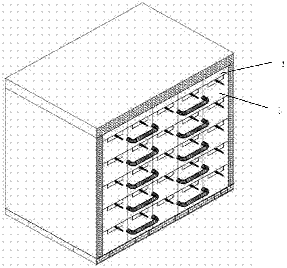
[0042] Such as figure 1 As shown, in this embodiment, the high-temperature heat storage valley energy utilization device using magnesia-iron bricks to encapsulate molten salt is composed of three parts, which are the heat storage pile constructed by the sensible-latent heat storage unit, and the power plant using valley electricity as the heat source. A heating unit and a heat exchange unit for realizing heat extraction. Specifically, each part is as follows:

[0043] Regenerative pile: including sensible-latent heat storage unit 3, the heat storage unit includes prefabricated solid heat storage brick 12 and molten salt unit 13, the main material of solid heat storage brick 12 is clay, magnesium iron and other metal materials powder or ...


PUM

PropertyMeasurementUnit
freezing pointaaaaaaaaaa
densityaaaaaaaaaa

Abstract

The invention discloses a high-temperature thermal storage valley energy utilization device with fused salt packaged by ferro magnesium bricks. The high-temperature thermal storage valley energy utilization device comprises a thermal storage pile, electric heating units and a heat exchange part. The thermal storage pile is built by a plurality of thermal storage units. Each thermal storage unit is a cube formed by packaging the fused salt in the corresponding hollow ferro magnesium brick, and rectangular channels and pipeline hole channels are reserved. A plurality of high-temperature-resisting heat preservation layers are arranged at the top of the thermal storage pile and in the circumferential direction of the thermal storage pile. Heat preservation materials of different temperature-resisting stages are selected according to different temperature distribution modes. Refractory bricks are used at the bottom of the thermal storage pile as the bearing structure of the whole thermal storage pile. Each electric heating unit comprises a heat conduction plate and electric heating devices at the two ends of the heat conduction plate, and the electric heating units are arranged in the rectangular channels of the thermal storage units. The heat exchange part comprises a heat conduction oil heat exchange coil, a primary side heat conduction oil circulating pump and a heat exchanger. The high-temperature thermal storage valley energy utilization device is used for high-temperature thermal energy storage, electric energy during the trough time period is converted into heat energy to be stored, and domestic hot water or heating heat is provided for users.

Description

technical field [0001] The invention belongs to the field of environmental protection energy storage, and in particular relates to a high-temperature heat storage valley energy utilization device using magnesia-iron bricks to encapsulate molten salt. Background technique [0002] With the changes in my country's industrial structure and the improvement of people's living standards, the peak power consumption during the day continues to increase, and the power consumption during the low valley hours at night decreases significantly. The peak-valley difference in power supply increases year by year, which brings great difficulties to the stable operation of the power grid. Due to the insufficient consumption of valley electricity, a large amount of waste of electric energy has also been caused. The application of energy storage technology separates power generation and power consumption from time and space. The power generated by the power plant no longer needs to be transmitte...

Claims


Application Information

Patent Timeline
Patent Type & Authority Patents(China)
IPC IPC(8): F24H7/04F24H9/00F24H9/18F24H9/20F28D20/02
CPCY02E60/14
Inventor 陆勇段文军鹿浩伟钟文琪
Owner SOUTHEAST UNIV
Why Eureka
Try Eureka