
Trans-horizon wireless communication system using the tropospheric evaporation duct

a wireless communication and tropospheric evaporation technology, applied in the field of wireless communication methods and systems, can solve the problems of insufficient infrastructure, inability to extend trans-horizon wireless communication, and inability to use land or sea, etc., to achieve high availability and/or capacity.

Active Publication Date: 2019-09-26
GASOLINEIAM NASIONAL BERHAD
View PDF1 Cites 3 Cited by
  • Summary
  • Abstract
  • Description
  • Claims
  • Application Information

AI Technical Summary

Benefits of technology

This patent describes a system for wireless communication over a sea using a special duct. The system includes multiple antennas and adaptive modulation and demodulation circuits at each end of the link. These circuits work together with the antennas to improve system performance by overcoming challenges such as fading and high pathloss. The result is a high availability and capacity for wireless communication in the evaporation duct, regardless of the environmental conditions.

Problems solved by technology

Wireless communication beyond line-of-sight (LOS) is generally not possible over either land or sea.
Over the sea or the ocean or any large bodies of water (such as large lakes), however, such infrastructure is nonexistent due to difficulty of installations in the water.
While line-of-sight based wireless communication using microwave radio can be established over the ocean, prohibitively high cost infrastructure is required in the middle of the ocean for extending trans-horizon wireless communication.
Satellite communication can facilitate such communication, however, over the sea, there are serious limitations such as high cost, data rate and traffic limitations and availability.
However, such systems have been unable to show establishment of neither a reliable communication link nor a high data rate throughput which can match a satellite or a LOS microwave-based broadband link.

Method used


Image

  • Trans-horizon wireless communication system using the tropospheric evaporation duct
  • Trans-horizon wireless communication system using the tropospheric evaporation duct
  • Trans-horizon wireless communication system using the tropospheric evaporation duct

Examples


Embodiment Construction

[0027]The following detailed description is merely exemplary in nature and is not intended to limit the invention or the application and uses of the invention. Furthermore, there is no intention to be bound by any theory presented in the preceding background of the invention or the following detailed description. It is the intent of the present embodiment to present a reliable wireless communication system for trans-horizon communication over the sea using the tropospheric evaporation duct.

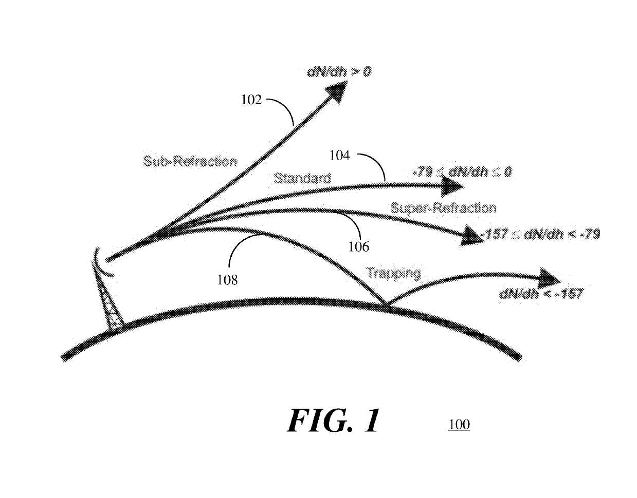
[0028]Referring to FIG. 1, an illustration 100 depicts four refractive conditions which depend upon refractive gradients. In standard conditions 102, the gradient of refractivity varies from 0 to −79 N-units per km. When the refractivity gradient varies from −79 to −157 N-units per km, a super-refraction condition 104 occurs in the troposphere and the ray will refract downwards at a rate greater than standard but less than the curvature of earth. If the refractivity gradient is greater than 0 N-un...


PUM


Abstract

A system for trans-horizon tropospheric-based wireless communication is provided. The system provides high availability and capacity as compared to a line-of-sight (LOS) standard microwave radio link while using very low height antenna towers. The system includes n×n MIMO transceiver circuitry and two or more antennas and adaptive modulation and demodulation in response to slow varying pathloss. Each of the two or more antennas is located at a vertical height above an average sea mean level within the evaporation duct. Availability percentage for different pathloss ranges along with adaptive modulation contributes to the overall availability according to the varying evaporation duct height.

Description

TECHNICAL FIELD[0001]The present invention generally relates to methods and systems for wireless communication, and more particularly relates to methods and systems for trans-horizon wireless communication using the tropospheric evaporation duct over the sea or the ocean.BACKGROUND OF THE DISCLOSURE[0002]Wireless communication requires a transmitter, a receiver and a communication channel. Wireless communication beyond line-of-sight (LOS) is generally not possible over either land or sea. Over land, the communication link can be extended by repeaters and landline connections to increase the range for trans-horizon distances. Over the sea or the ocean or any large bodies of water (such as large lakes), however, such infrastructure is nonexistent due to difficulty of installations in the water. While line-of-sight based wireless communication using microwave radio can be established over the ocean, prohibitively high cost infrastructure is required in the middle of the ocean for exten...

Claims


Application Information

Patent Timeline
IPC IPC(8): H04B7/02H04B7/10H04B7/024H04B7/0413H04B1/7115
CPCH04B7/028H04B1/7115H04B7/0413H04B7/10H04B7/024
Inventor JEOTI, VARUNIQBAL, ASIFZAIDI, KHURRAM SHABIHDRIEBERG, MICHAELWONG, PENG WENOSMAN, M SHARIF
Owner GASOLINEIAM NASIONAL BERHAD
Learn More