
Method and apparatus for evaluating damage to magnetic linear body

a technology of damage detection and wire rope, which is applied in the direction of rope making machines, control, and papermaking, etc., can solve the problems of incongruous output signals of inspection devices, unfavorable inspection of inability to detect magnetic flux leaked from damaged parts of wire rope. , to achieve the effect of smooth movement of portable damage detection devices

Active Publication Date: 2019-09-26
TOKYO ROPE MFG
View PDF0 Cites 2 Cited by
  • Summary
  • Abstract
  • Description
  • Claims
  • Application Information

AI Technical Summary

Benefits of technology

This patent aims to improve the signal-to-noise ratio and prevent damage to wire rope caused by magnetic detection devices. The invention ensures an equal magnetization of the wire rope over the entire circumference while maintaining a distance between the wire rope and the magnetizing device. Additionally, the wire rope is not in contact with the damage detection device, preventing any damage caused by contact. Overall, this results in a more accurate and reliable detection of damage in wire rope.

Problems solved by technology

In the magnetic flux leakage method, a wire rope is magnetized in the longitudinal direction by using magnets of the inspection device, and magnetic flux leaked from a damaged part of the wire rope is detected.
Therefore, when magnetic force of the magnets provided in the inspection device is weak, the magnetizing directions (magnetic axes) of the wire rope in an inspection range are not uniform due to an influence of the magnetic poles of both the end portions of the wire rope.
As a result, output signals of the inspection device, in particular, output signals of both end parts of the inspection range may be unstable (S / N ratio may be deteriorated).
However, since magnets having strong magnetic force are heavy, the inspection device is less easily conveyed.

Method used


Image

  • Method and apparatus for evaluating damage to magnetic linear body
  • Method and apparatus for evaluating damage to magnetic linear body
  • Method and apparatus for evaluating damage to magnetic linear body

Examples


Embodiment Construction

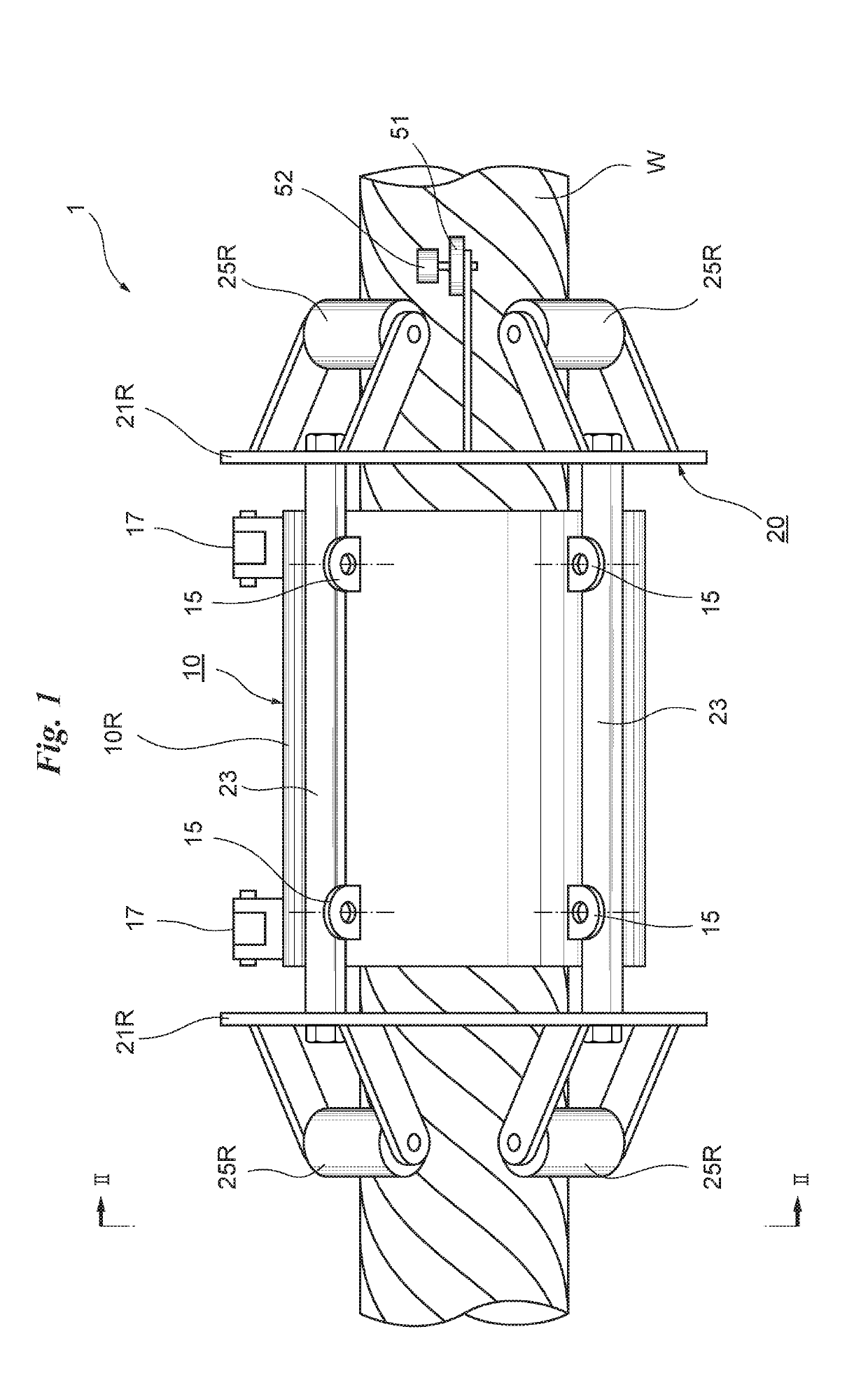
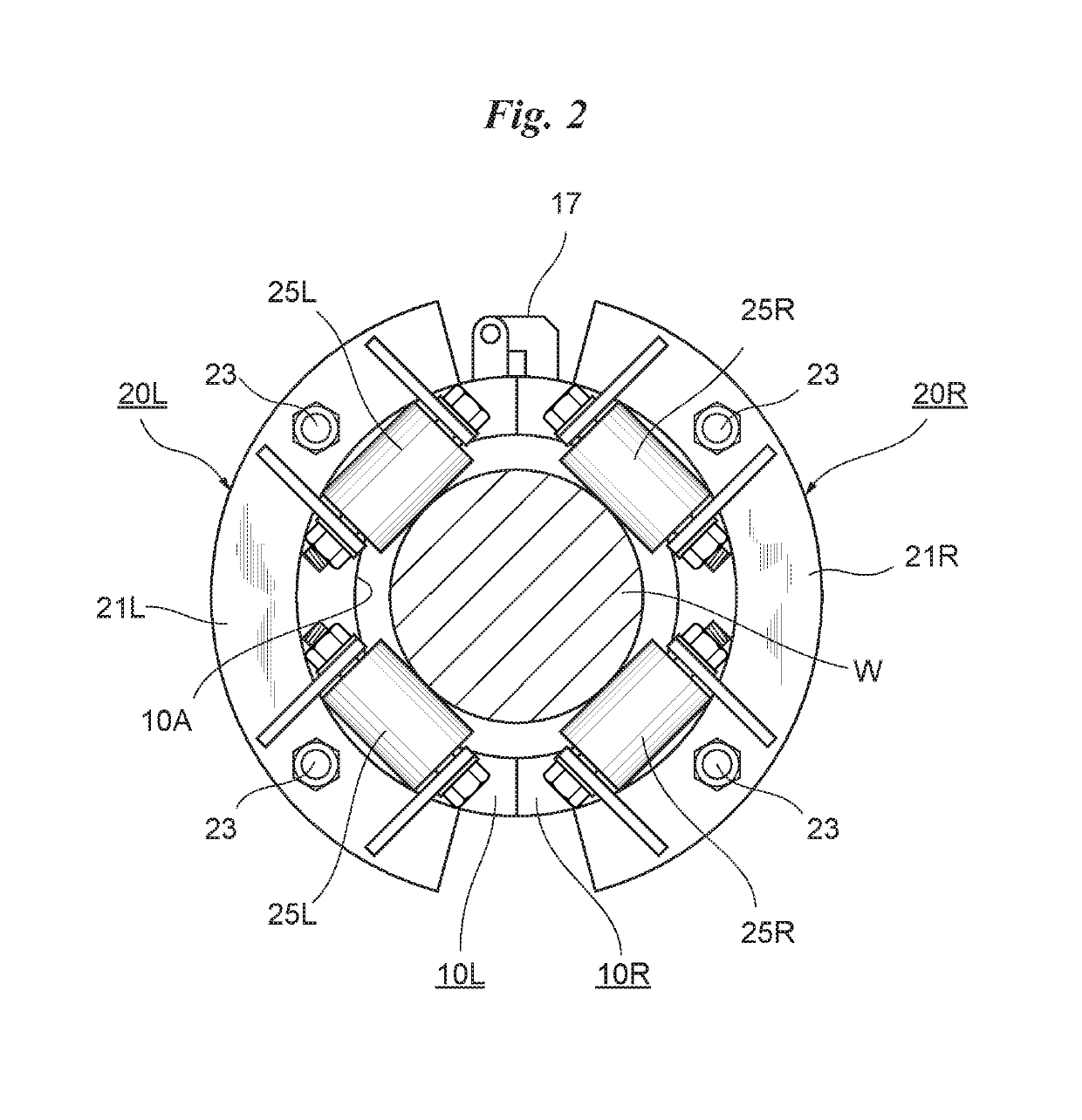
[0031]FIG. 1 is a front view of a portable wire rope damage detection device. FIG. 2 is a side view of the portable wire rope damage detection device along the line II-II of FIG. 1.

[0032]A portable wire rope damage detection device 1 includes a magnetic detector 10, and a moving mechanism 20 for moving the magnetic detector 10 along a wire rope W.

[0033]The magnetic detector 10 is formed in a cylindrical shape, and includes a columnar internal space 10A through which the wire rope W passes, the internal space having a diameter larger than a diameter of the wire rope W. The magnetic detector 10 includes a pair of openable / closable half-cylindrical bodies 10L, 10R coupled at two hinges 17 which are provided and spaced from each other in the front and back direction (cylindrical axis direction), and the half-cylindrical bodies 10L, 10R can be opened to both sides on the hinges 17. By enclosing (embracing) the wire rope W from both the sides by the two half-cylindrical bodies 10L, 10R, t...


PUM


Abstract

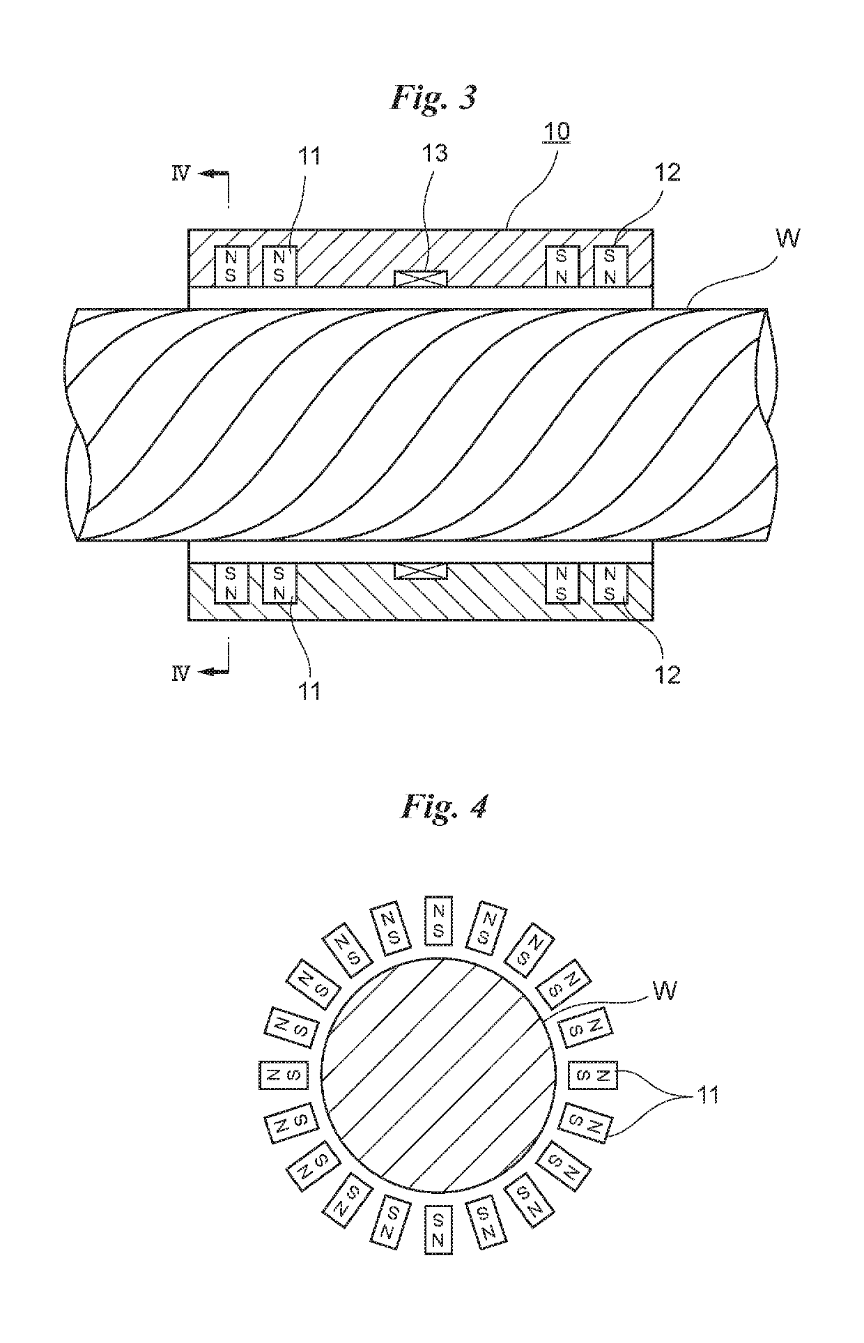
A magnetic detector includes permanent magnets that magnetize a wire rope W in the longitudinal direction, and a search coil that detects a change in the cross sectional area of the wire rope W magnetized by the permanent magnets. The magnetic detector is provided so as to surround a part of the wire rope W. Prior to inspection, the magnetic detector is moved back and forth at least three times across an inspection range of the wire rope W. After the magnetic detector is moved back and forth, the change in the cross sectional area, that is, damage to the wire rope W is inspected by using signals outputted from the search coil.

Description

CROSS REFERENCE TO RELATED APPLICATIONS[0001]This application is a Continuation Application of PCT International Application No. PCT / JP2016 / 087019 filed on Dec. 13, 2016, the entire disclosure of the application being considered part of the disclosure of this application and hereby incorporated by reference.TECHNICAL FIELD[0002]The present invention relates to a damage detection method of a wire rope, and a signal processor and a damage detection device used for damage detection of a wire rope.BACKGROUND ART[0003]Japanese Patent Application (Laid-Open No. 2002-5896) discloses an inspection device that inspects a wire rope by using the magnetic flux leakage method.[0004]In the magnetic flux leakage method, a wire rope is magnetized in the longitudinal direction by using magnets of the inspection device, and magnetic flux leaked from a damaged part of the wire rope is detected. An elongated magnetic body such as a wire rope may be magnetized due to an influence of earth magnetism duri...

Claims


Application Information

Patent Timeline
IPC IPC(8): G01N27/83
CPCG01N27/83D07B7/16D07B1/145D07B2301/555
Inventor ITOI, HIROAKISHIIKI, SADANORISUGAHARA, MASAMICHIMORIYA, TOSHIYUKI
Owner TOKYO ROPE MFG
Learn More