
Apparatus for detecting moisture based on signal outputted from heat flow sensor

Inactive Publication Date: 2019-09-26
DENSO WAVE INC
View PDF0 Cites 0 Cited by
  • Summary
  • Abstract
  • Description
  • Claims
  • Application Information

AI Technical Summary

Benefits of technology

The patent describes a moisture detection apparatus that is housed in a case and does not affected by static electricity or corrosion. The apparatus detects moisture based on the flow of heat, even if there is a metal structure or static electricity present in the periphery. The detection surface is composed of a metallic material, which has high thermal conductivity and reduces the risk of erroneous detection. It includes a spacer that separates the detection surface from the setup surface, preventing the absorption of heat from the surface and reducing the heat generated by the heat source. Overall, the moisture detection apparatus is highly efficient and versatile.

Problems solved by technology

However, in the case of the capacitance-type moisture detection apparatus, when a metal component is present in the periphery of a detecting unit, erroneous detection may occur.
Therefore, a problem arises in that a setup location of the capacitance-type moisture detection apparatus and a subject on which moisture detection is to be performed are limited.
In addition, in the case of the capacitance-type moisture detection apparatus, a problem arises in that the capacitance-type moisture detection apparatus is unsuitable for setup in locations in which static electricity is generated.
Furthermore, in the case of the resistance-type moisture detection apparatus, a detecting unit is required to be exposed.
Therefore, a problem arises in that the detecting unit may become corroded as a result of contact with moisture.
Consequently, the moisture detection apparatus is unaffected by static electricity.

Method used


Image

  • Apparatus for detecting moisture based on signal outputted from heat flow sensor
  • Apparatus for detecting moisture based on signal outputted from heat flow sensor
  • Apparatus for detecting moisture based on signal outputted from heat flow sensor

Examples


Embodiment Construction

[0019]An embodiment of the present invention will hereinafter be described with reference to the drawings.

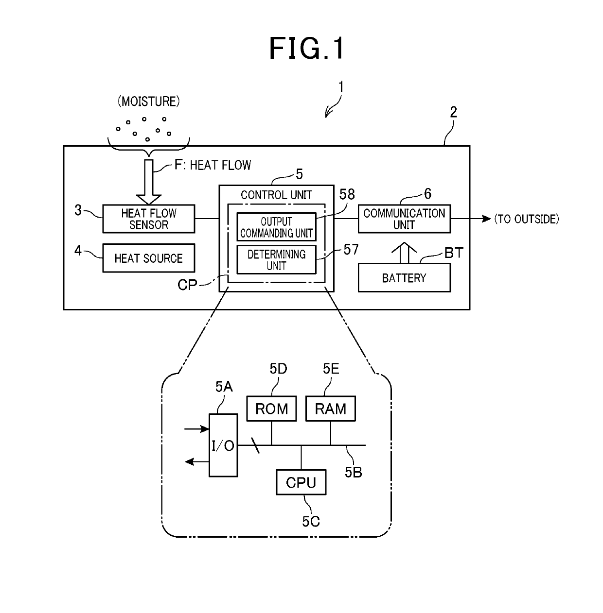
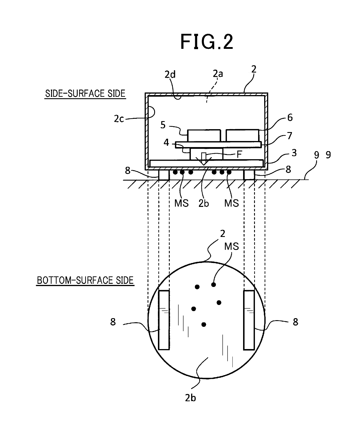
[0020]As shown in FIG. 1, in a moisture detection apparatus (i.e., an apparatus for detecting moisture) 1 according to the present embodiment, a heat flow sensor 3, a heat source 4, a control unit 5, a communication unit 6, and the like are housed in a watertight manner in a case 2. According to the present embodiment, setup of the moisture detection apparatus 1 is assumed to be on a surface of a metal pipe through which a liquid, such as water, flows.

[0021]According to the present embodiment, the case 2 is formed into a hollow, circular columnar shape having a diameter of approximately several centimeters. The case 2 is composed of a metal material that is resistant to corrosion and has higher thermal conductivity than air. However, for example, a wall surface 2c and an upper surface 2d of the case 2 may be composed of a resin material. That is, the case 2 is merely required to...


PUM


Abstract

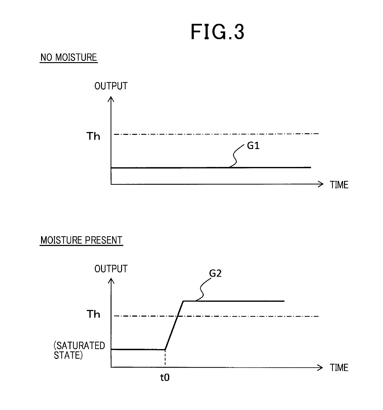
A moisture detection apparatus is equipped with a case having a detection surface. The apparatus includes a heat flow sensor provided to be in contact with the detection surface, a heat source provided on a side facing the detection surface with the heat flow sensor therebetween, and a determining unit. The heat flow censer, the heat source, and the determining unit are housed in the case. The heat flow sensor is oriented to detect a flow of heat from the heat source towards the detection surface. The heat source generates heat at all times at an amount that enables the heat flow sensor to be in a thermally saturated state in a state where moisture is not attached to an outer side of the detection surface. The the determining unit determines that moisture is detected when an output from the heat flow sensor changes such as to exceed a threshold.

Description

CROSS-REFERENCE TO RELATED APPLICATION[0001]This application is based on and claims the benefit of priority from earlier Japanese Patent Application No. 2018-052529 filed on Mar. 20, 2018, the description of which is incorporated herein by reference.BACKGROUNDTechnical Field[0002]The present invention relates to an apparatus for detecting moisture, and in particular, to the apparatus which is provided with a heat flow sensor and configured to detect moisture based on a signal outputted from the heat flow sensor.Related Art[0003]Conventionally, a moisture detection apparatus that detects water leakage from a pipe or the like is known. For example, a capacitance type and a resistance type are known as such a moisture detection apparatus. The capacitance-type moisture detection apparatus detects moisture based on changes in capacitance, as described in JP-A-2002-357582. The resistance-type moisture detection apparatus detects moisture based on changes in electrical resistance.[0004]How...

Claims


Application Information

Patent Timeline
IPC IPC(8): G01N25/56G01K17/06G01M3/00
CPCG01M3/002G01K17/06G01N25/56G01M3/16
Inventor NAKAJIMA, KENSUKE
Owner DENSO WAVE INC
Learn More