
Oil system

a technology of oil system and oil pump, which is applied in the direction of turbines, machines/engines, efficient propulsion technologies, etc., can solve the problems of oil system loss, gearbox damage, gearbox bearing damage, etc., to facilitate the electric pump, reduce power/energy requirements, and facilitate the effect of electric pump

Active Publication Date: 2019-09-26
ROLLS ROYCE PLC +1
View PDF0 Cites 7 Cited by
  • Summary
  • Abstract
  • Description
  • Claims
  • Application Information

AI Technical Summary

Benefits of technology

The invention reduces damage to the bearings of a gearbox, which prevents excessive drag on the airframe caused by a locked fan or propeller. It also allows for system checks and adjustments of oil flow rate based on windmilling speeds or gearbox oil pressure.

Problems solved by technology

However, if an in-flight event results in engine shut-down, the oil system loses power and the gearbox may not be properly lubricated.
As airflow through a fan or propeller of a moving aircraft drives continued rotation of the fan or propeller, the gearbox may be damaged and / or may seize if not properly lubricated, potentially leading to a hazard.
Bearings of a gearbox may therefore suffer more damage in a shorter timeframe, as compared to windmilling whilst parked.
As a result, a system designed to manage ground windmilling would not generally be capable of providing in flight protection.
Some failure cases of the gearbox can lead to hazardous conditions for the aircraft unless protection systems are put in place.
The auxiliary oil system has its own pump, as a pump of the primary system (driven by the engine; usually by the high pressure spool thereof), will not provide flow in windmill conditions, or may itself have failed.
With a mechanical pump, operation of the pump is continuous whilst the shaft is rotating / engine is active; this may lead to challenges in meeting reliability requirements.
Unless the flow from the pump is utilised, this power is a loss from the cycle.
Utilising the flow whilst keeping the auxiliary system independent of the main system may present different challenges.
This potentially results in a pump far larger than one based on an electric system.
As compared to a system using a mechanical pump, fewer valves may be required (which can be points of failure).

Method used


Image

  • Oil system
  • Oil system
  • Oil system

Examples


Embodiment Construction

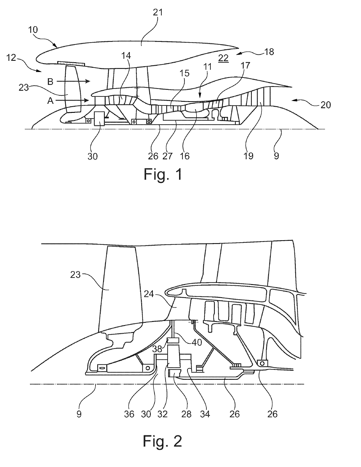
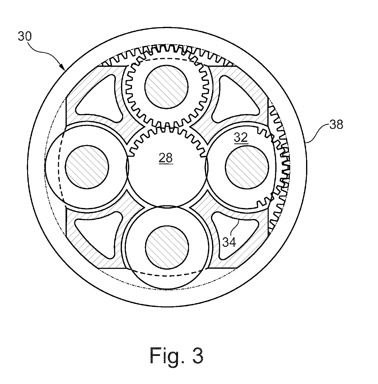
[0133]FIG. 1 illustrates a gas turbine engine 10 having a principal rotational axis 9. The engine 10 comprises an air intake 12 and a propulsive fan 23 that generates two airflows: a core airflow A and a bypass airflow B. The gas turbine engine 10 comprises a core 11 that receives the core airflow A. The engine core 11 comprises, in axial flow series, a low pressure compressor 14, a high-pressure compressor 15, combustion equipment 16, a high-pressure turbine 17, a low pressure turbine 19 and a core exhaust nozzle 20. A nacelle 21 surrounds the gas turbine engine 10 and defines a bypass duct 22 and a bypass exhaust nozzle 18. The bypass airflow B flows through the bypass duct 22. The fan 23 is attached to and driven by the low pressure turbine 19 via a shaft 26 and an epicyclic gearbox 30.

[0134]In use, the core airflow A is accelerated and compressed by the low pressure compressor 14 and directed into the high pressure compressor 15 where further compression takes place. The compres...


PUM


Abstract

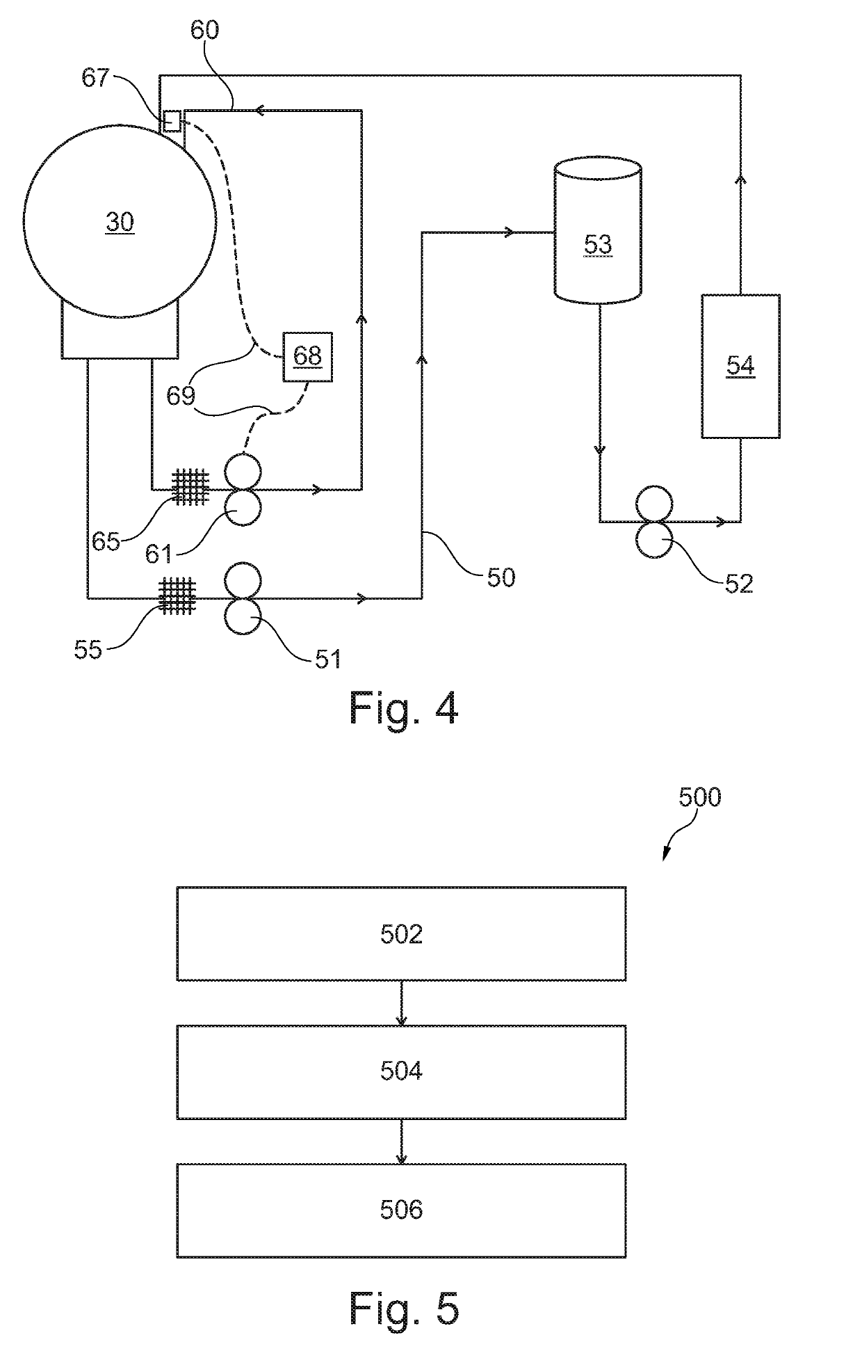
A method (500) and apparatus (50, 60) for lubrication of a gearbox (30) of an aircraft engine comprise provision (502) of oil to the gearbox (30) through a primary oil system (50) driven by a core (11) of the engine (10) in normal conditions; detection (504) of windmilling conditions and / or failure of the primary oil system (50); and in response to the detected condition or failure, activation (506) of an electric pump (61) of an auxiliary oil system (60), to provide oil to the gearbox (30).

Description

CROSS-REFERENCE TO RELATED APPLICATIONS[0001]This application is based upon and claims the benefit of priority from British Patent Application Number 1804506.2 filed 21 Mar. 2018, the entire contents of which are incorporated by reference.BACKGROUND1. Field of the Disclosure[0002]The present disclosure relates to an auxiliary oil system for an aircraft engine, and more specifically to an auxiliary oil system arranged to protect a gearbox of an aircraft engine, such as a gas turbine engine, during windmill conditions whilst the aircraft is in flight.2. Description of the Related Art[0003]Known aircraft engines include oil systems mechanically driven by the engine and arranged to lubricate / cool elements of the engine including gearbox bearings. However, if an in-flight event results in engine shut-down, the oil system loses power and the gearbox may not be properly lubricated. As airflow through a fan or propeller of a moving aircraft drives continued rotation of the fan or propeller,...

Claims


Application Information

Patent Timeline
Patent Type & Authority Applications(United States)
IPC IPC(8): F01D25/20F16H57/04
CPCF16H57/0476F16H57/0471F01D25/20F16H57/048F01D21/14F01M1/02F01M1/18F01M2001/0215F01M2001/123F02C7/36F05D2260/40311F05D2260/98F05D2270/09F05D2270/301F16H57/0442F16N2210/02F16N2210/14F16N2260/20Y02T50/60F02C7/06
Inventor MASON, JOHN RASTLEY, THOMAS PHILIP
Owner ROLLS ROYCE PLC
Learn More