
Method And Apparatus For Separation Of A Substance From Groundwater

a technology of groundwater and apparatus, applied in the direction of water/sewage treatment by ion exchange, transportation and packaging, borehole/well accessories, etc., can solve the problems of contaminated soils, groundwater and drinking water supplies, and techniques that do not work to treat groundwater with pfas contamination, etc., to achieve adequate froth layer, adequate froth layer, and adequate drainage characteristics

Active Publication Date: 2019-08-29
OPEC REMEDIATION TECH PTY LTD
View PDF0 Cites 4 Cited by
  • Summary
  • Abstract
  • Description
  • Claims
  • Application Information

AI Technical Summary

Benefits of technology

The patent text describes a device that can regulate the depth of a froth layer in a well to improve the drainage of the substance. The device can be positioned at different locations in the well and can be self-locating. It can also contain a secondary treatment device to further reduce the volume of concentrate that needs to be transported or treated. The main body of the device can be moved within the well to maintain the depth of the froth layer. The device has a skirt that can block the outlet of groundwater in the well. The technical effects of this invention include improved drainage of the substance, reduced concentration of the substance, and efficient treatment of the concentrate.

Problems solved by technology

They are recalcitrant, bio-accumulative and known to have contaminated soils, groundwaters and drinking water supplies.
PFAS are known to have contaminated groundwater, including drinking water supplies.
However, it is also known that such techniques do not work to treat groundwater with PFAS contamination.
While they are soluble, most long-chain PFAS (including PFOS and PFOA have a low, to very low, vapour pressure, which means they do not volatilise easily, so air-stripping is therefore not an ineffective remedial treatment.
This technique is costly because of the expense of transporting large quantities of water from place to place.
In general, the treatment agents used in these technologies cannot be easily regenerated and require disposal (typically to landfill) after they have reached maximum capacity.
Pump and treat systems are usually required to operate for extended periods over many years, and the treatment volumes are very large—as a result, the treatment plant equipment is also large.
Capital and operating costs are typically high due to treatment plant size and long operational time periods (years, or even decades).
The other difficulty is that contaminants can be absorbed onto non-permeable materials in the ground (for example, onto silt or clay), and may never be properly released.
However, PFAS are recalcitrant, and laboratory studies have found limited success with performance of these reagents.
Such wells can involve complex, multiple screen sections in side walls, which may need to be separated by packers or low permeability barriers.
It has become apparent that there are no suitable technologies which overcome the cost and scale disadvantages of pump and treat remediation.
It has also become apparent that in-situ chemical treatment to neutralise PFAS has yet to be successfully proven, and this process poses other environmental risks due to the presence of residual substances and their effects on subsurface media.
It is undesirable in such situations to return treated groundwater which may still contain some level of residual contaminant as it is exiting the elongate chamber of the well, into an uppermost ground layer which is initially entirely uncontaminated.
In other situations, it may not be physically possible to take groundwater for treatment out of semi and confined aquifers and then try to release it for circulation to occur through an aquitard or aquiclude.
If too much gas is introduced into the well, the flow of groundwater can move away from its ideal treatment condition of quiescent flow, and instead become turbulent.
In turbulent situations, the froth layer can become disrupted and can also become very wet and thus cause dilution of the concentration of the substance that is being removed from the groundwater
In some places, environmental restrictions mandate that water taken out of the ground cannot be treated above-ground and then returned back to the immediate area of ground, which means that the groundwater portion of any contaminant concentrate, even if successfully decontaminated, cannot be reused on the site, but must be transported away.
In one form of this, the said device controls the cross-sectional flow path of the froth in the chamber, resulting in froth confinement and drainage.

Method used


Image

  • Method And Apparatus For Separation Of A Substance From Groundwater
  • Method And Apparatus For Separation Of A Substance From Groundwater
  • Method And Apparatus For Separation Of A Substance From Groundwater

Examples


Embodiment Construction

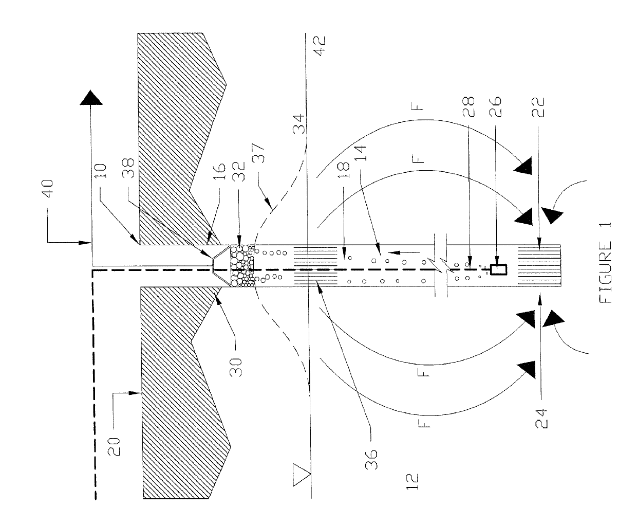
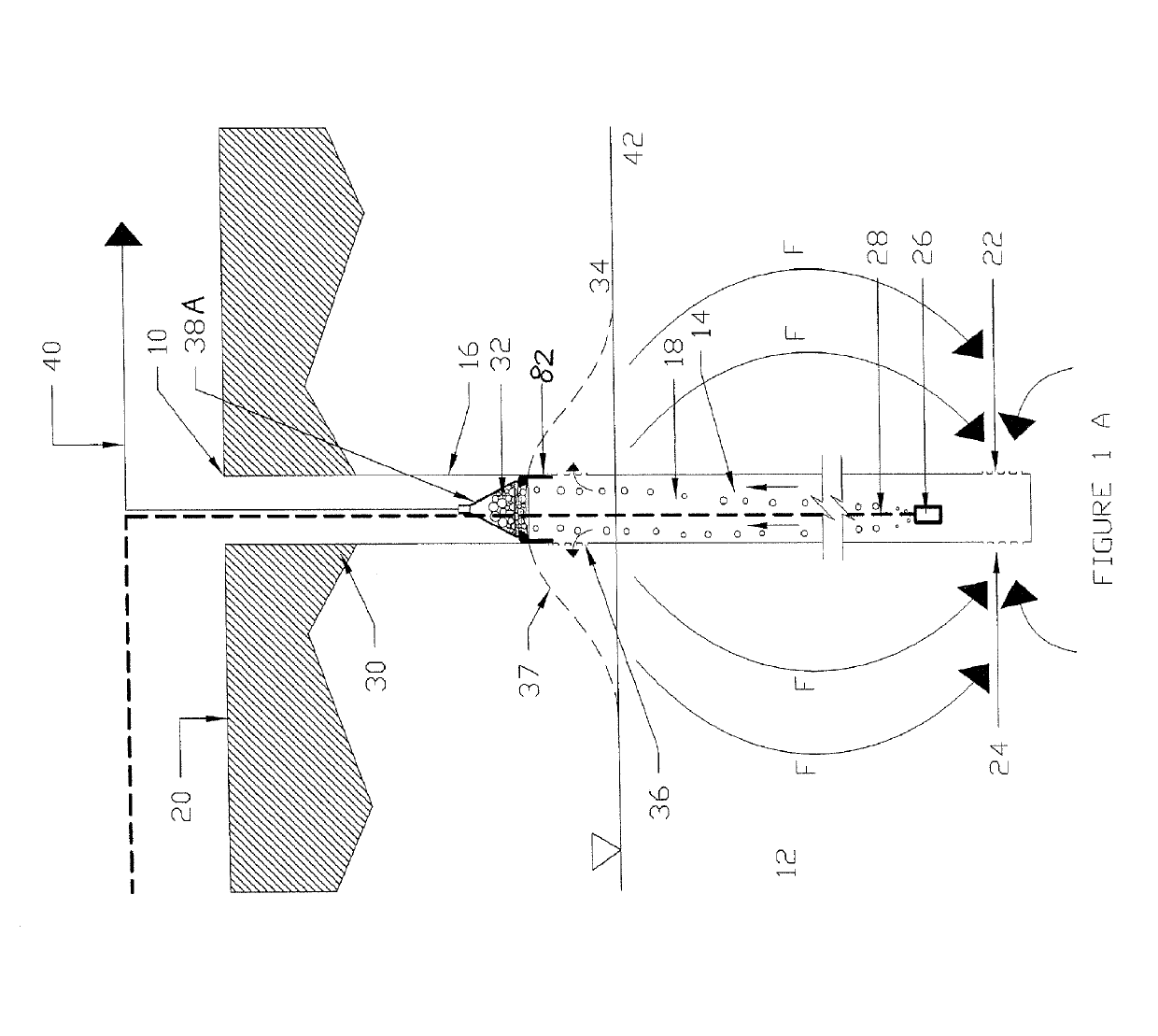
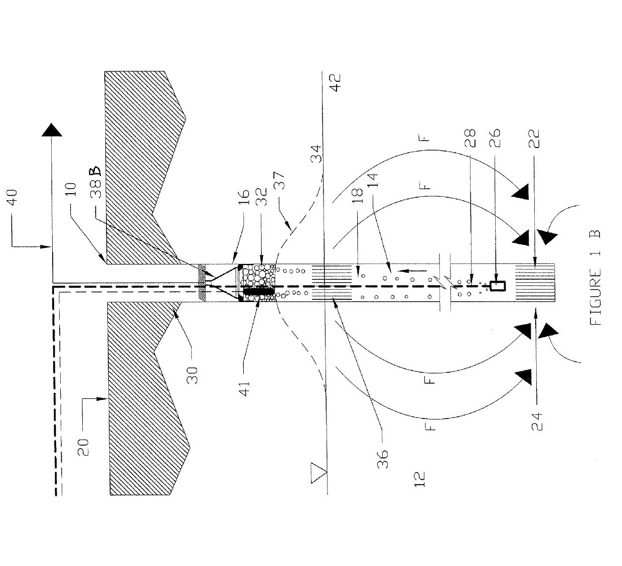
[0078]This disclosure relates to the features of a groundwater well 10 and its use for removal of an organic contaminant from the surrounding ground 12, for instance in an unconfined or a semi-confined aquifer. Referring to the embodiment disclosed in FIG. 1, the well body 14 is in the form of an elongate, cylindrical column 16 having an interior chamber 18. The well body 14 is circular in cross-section and is positioned within the ground 12, below the ground surface level 20. The well body 14 can be a tube or column casing 16 which is made of hard plastic or metal sufficient to withstand the hydraulic pressure at depths into the ground, and sufficiently structurally sound so that it will not collapse or corrode. In one example, the column 16 has an internal bore of 150 millimetres and reaches an overall depth below the ground surface level 20 of 5 metres, although these dimensions are exemplary only, and depend on the particular site being treated.

[0079]The chamber 18 has a screene...


PUM

PropertyMeasurementUnit
depthaaaaaaaaaa
depthaaaaaaaaaa
concentrationaaaaaaaaaa

Abstract

Apparatus is disclosed for separating an amount of a substance from groundwater, comprising an elongate chamber (18) having an inlet (22) which is arranged in use to admit groundwater into the chamber near a lower first end (24). There is also a gas sparger (26) located near the first end (24) which admits gas into the chamber for inducing groundwater to flow from the first end (24) of the chamber toward a second end upper end, and for producing a froth layer (32) which rises above an interface with the groundwater including a concentrated amount of the substance. A suction hood (38) can be moved downward from the top of the chamber (18) into a position to collapse the froth layer (32) and to cause it to be removed from the well body (14). The suction hood (38) (acting as a froth depth regulation device) controls the amount of groundwater in the froth layer (32), which influences the concentration of the contaminant substance achieved in the froth layer (32).

Description

TECHNICAL FIELD[0001]This disclosure relates to an apparatus for separation of a substance from groundwater and to a method for use of the separation apparatus. In one form, the apparatus and method can be applied to removal of contaminant organic material present in groundwater which is located in a body of ground. However, the apparatus and method can also be applied to the removal of non-organic materials or contaminants from groundwater.BACKGROUND OF THE DISCLOSURE[0002]Perfluoroalkyl or polyfluoroalkyl substances (PFAS) embody a range of poly fluorinated alkyl substances (including but not limited to carboxylic acids, alkyl sulfonates, alkyl sulfonamido compounds and fluoro telemeric compounds of differing carbon chain lengths and precursors of these). PFAS have found use in a wide variety of applications including as a specialised fire-fighting product, or for impregnation or coating of textiles, leather and carpet, or for carpet cleaning compounds, as well as in aviation hydr...

Claims


Application Information

Patent Timeline
Patent Type & Authority Applications(United States)
IPC IPC(8): C02F1/24C02F1/28C02F1/44C02F1/00C02F1/42B09C1/00
CPCC02F1/281C02F1/283C02F1/441C02F1/008C02F1/42B09C2101/00B09C1/005B09C1/007C02F2101/36C02F2103/06C02F2209/38B09C1/002C02F1/24C02F1/58C02F1/00C02F2101/40C02F2101/34B03D1/24B01F23/231261B01F23/23123B01F23/237613B01F23/237612
Inventor PHILLIPS, STEVEN EDWARDBRICKLE, GREGORY RAYMONDBURNS, DAVID JOHN
Owner OPEC REMEDIATION TECH PTY LTD
Learn More