
Method for manufacturing bone graft material and bone graft material manufactured thereby

Active Publication Date: 2019-07-18
ELECTRONICS & TELECOMM RES INST +1
View PDF0 Cites 8 Cited by
  • Summary
  • Abstract
  • Description
  • Claims
  • Application Information

AI Technical Summary

Benefits of technology

The present invention is a method for manufacturing a bone graft material using a 3D printing technology of a digital lighting processing (DLP) system. This method improves the precision and design of the bone graft material by overcoming limitations of existing 3D printing methods. The technique involves developing a slurry of ceramic material and photocurable resin for use in 3D printing, resulting in bone graft materials with excellent compressive strength and precision. The invention aims to provide a better method for manufacturing bone graft materials using 3D printing technology.

Problems solved by technology

In this case, various variables may be generated during the surgery, and when the response to the variables goes wrong, it is difficult to expect a clinically good prognosis, and inconvenience may be caused to the patient.
Also, in the case of a particle-type (powder-type) bone graft material, it is difficult to obtain a sufficient bone volume after the surgery.
In order to solve the problem, a method of protecting a surgical site by introducing an excessive amount of bone graft material and using a shielding membrane is used, but there are disadvantages in that the surgical process is difficult to perform and the consumption of starting material is increased.
However, 3D printing studies related to ceramic materials are more difficult than polymeric materials, so that many studies are not being conducted.
This method is easy and can achieve a continuous output, but there are limitations such as deterioration in precision and restriction of design.

Method used


Image

  • Method for manufacturing bone graft material and bone graft material manufactured thereby
  • Method for manufacturing bone graft material and bone graft material manufactured thereby
  • Method for manufacturing bone graft material and bone graft material manufactured thereby

Examples


Embodiment Construction

[0037]Exemplary embodiments of the present invention will be described in detail below with reference to the accompanying drawings. While the present invention is shown and described in connection with exemplary embodiments thereof, it will be apparent to those skilled in the art that various modifications can be made without departing from the spirit and scope of the invention.

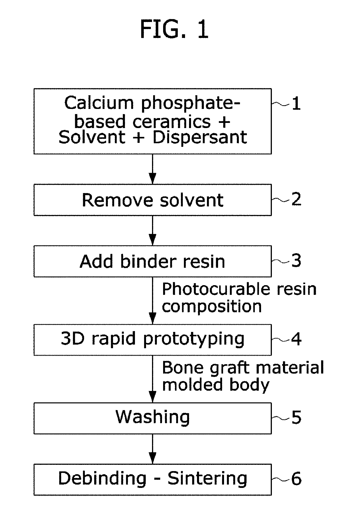
[0038]FIG. 1 is a process flowchart of a method for manufacturing a bone graft material of the present invention. The process is performed as follows.[0039][Step 1] dispersing a powder material including calcium phosphate-based ceramics including calcium and phosphorus (hereinafter, referred to as “a calcium phosphate-based ceramic material’) including calcium and phosphorus into a solvent by using a dispersant;[0040][Step 2] recovering the calcium phosphate-based ceramics by removing the solvent from a solution in which the calcium phosphate-based ceramic material is dispersed in Step 1;[0041][Step 3] produc...


PUM

PropertyMeasurementUnit
Temperatureaaaaaaaaaa

Abstract

The present invention relates to a method for manufacturing a bone graft material using 3D printing of a DLP system. The method includes (1) dispersing a powder material including calcium phosphate-based ceramics in a solvent; (2) recovering the calcium phosphate-based ceramics by removing the solvent from a solution in which the calcium phosphate-based ceramic material is dispersed in Step 1; (3) producing a photocurable resin composition by adding a binder resin including a crosslinking agent and a photoinitiator to the calcium phosphate-based ceramics obtained in Step 2; (4) performing 3D rapid prototyping on a bone graft material molded body from the composition for a bone graft material produced in Step 3 by 3D printing of a DLP system; and (5) debinding and sintering organic materials remaining in the bone graft material molded body subjected to prototyping in Step 4.

Description

CROSS-REFERENCE TO RELATED APPLICATION[0001]This application claims priority to and the benefit of Korean Patent Application No. 10-2018-0004840, filed on 15 Jan. 2018, the disclosure of which is incorporated herein by reference in its entirety.BACKGROUND1. Field of the Invention[0002]The present invention relates to a method for manufacturing a bone graft material by using a 3D layered prototyping method (3D printing), and a bone graft material manufactured by using the method.2. Discussion of Related Art[0003]It is common that the existing implant surgery uses diagnostic equipment to primarily confirm clinical information on the oral cavity of a patient and is performed with a final confirmation at the time of actual surgery. In this case, various variables may be generated during the surgery, and when the response to the variables goes wrong, it is difficult to expect a clinically good prognosis, and inconvenience may be caused to the patient. Further, bone augmentation using a b...

Claims


Application Information

Patent Timeline
IPC IPC(8): A61F2/46A61C13/00A61F2/28A61L27/12
CPCA61F2/4644A61C13/0019A61F2/28A61F2/4601A61L27/12A61L27/3608A61F2310/00359A61F2310/00796A61L27/32B33Y10/00A61F2310/00293B33Y70/00B33Y80/00A61L27/50A61L27/56A61L2430/02A61F2002/2835B29C64/314A61L27/46B29C64/129B29C64/364B33Y70/10
Inventor YANG, SO YOUNGCHUNG, YONG ILKIM, KYU HYUNGLEE, MIN JILEE, SOO INCHOI, EUN CHANG
Owner ELECTRONICS & TELECOMM RES INST
Learn More