Rotary compressor
a compressor and rotary technology, applied in the direction of rotary/oscillating piston pump components, machines/engines, liquid fuel engines, etc., to achieve the effect of reducing the distance from the lower cylinder to the muffler, simplifying the structure of the rotary compressor, and preventing interactive amplification of nois
- Summary
- Abstract
- Description
- Claims
- Application Information
AI Technical Summary
Benefits of technology
Problems solved by technology
Method used
Image
Examples
first embodiment
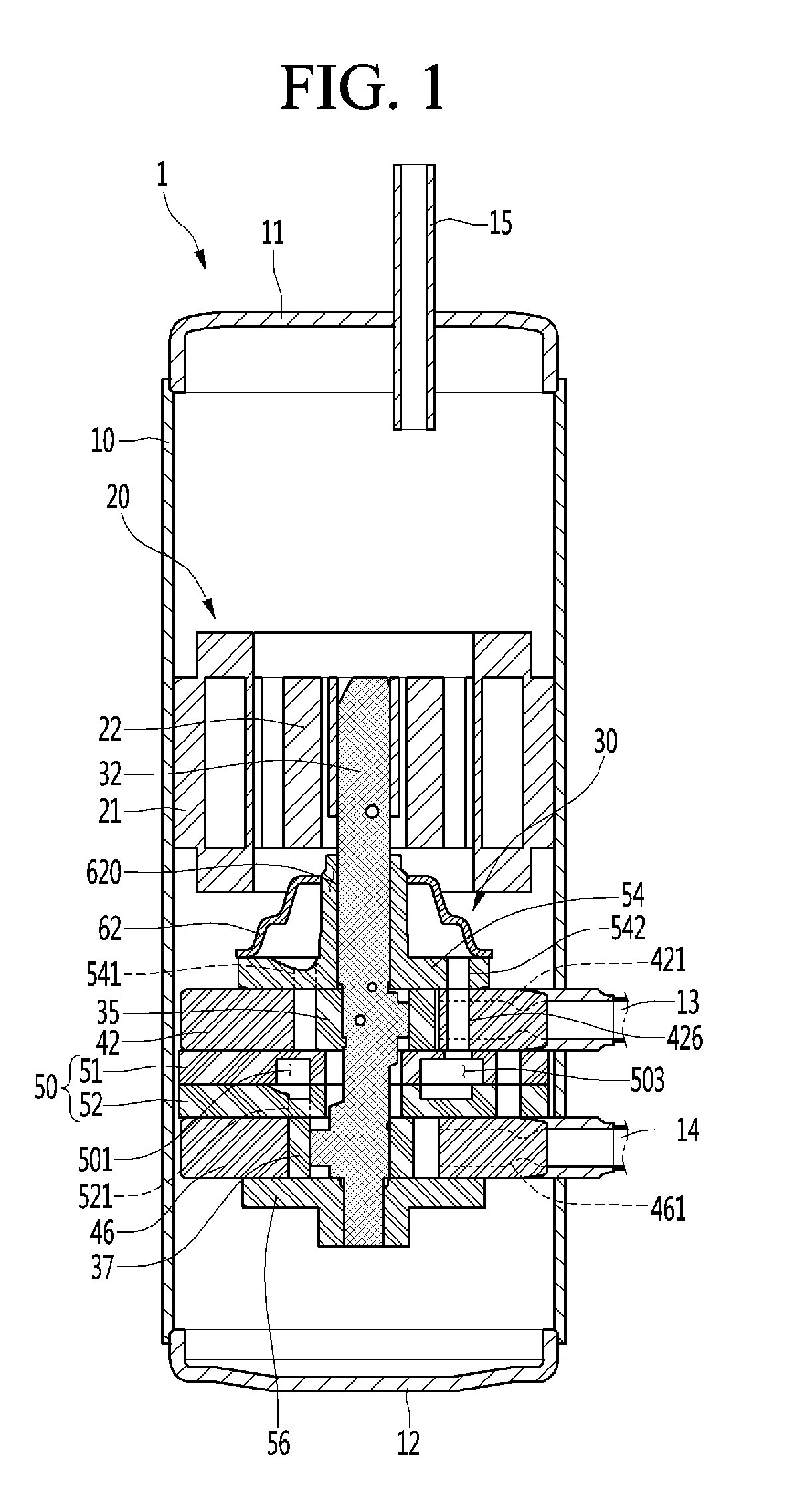
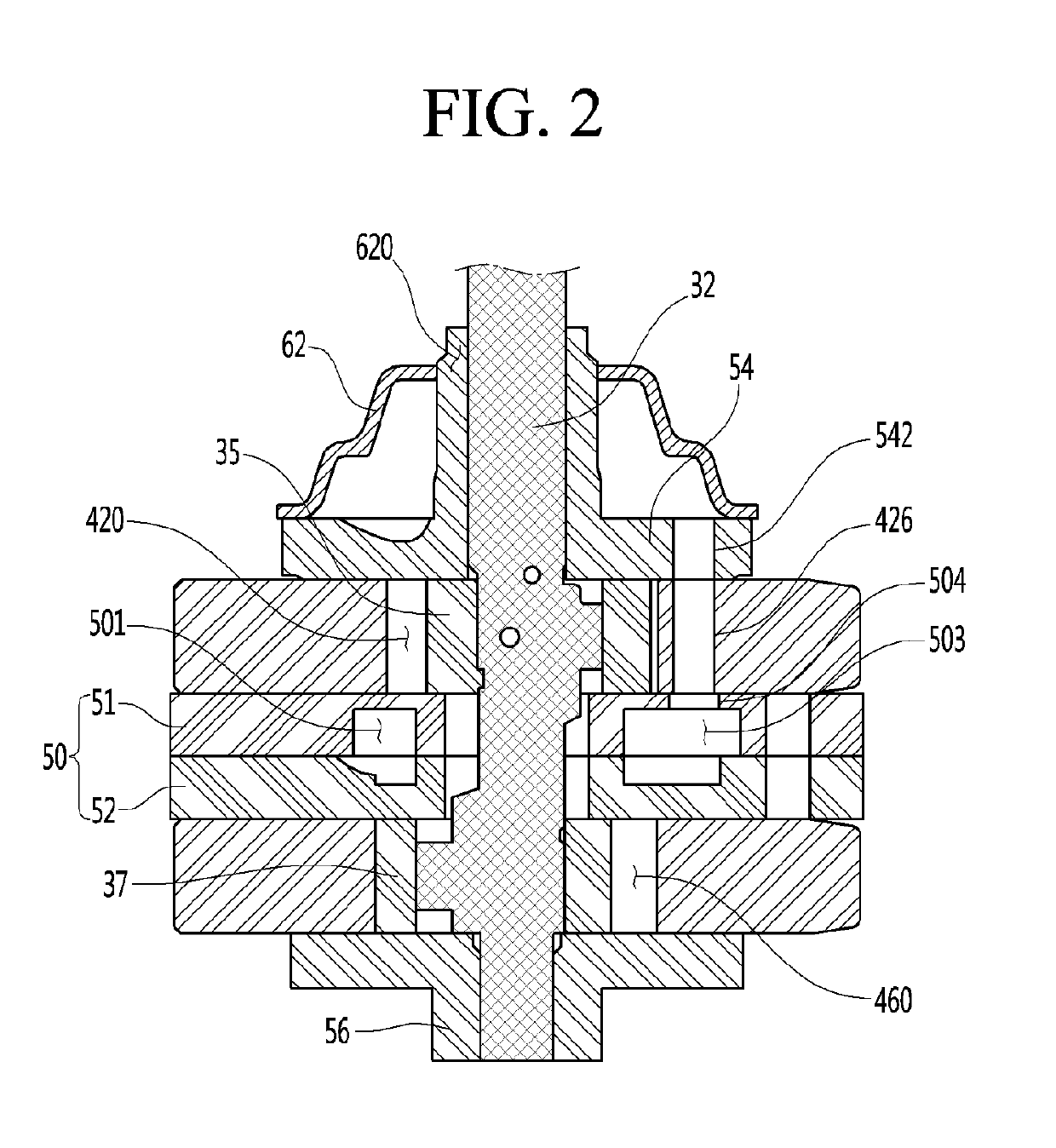
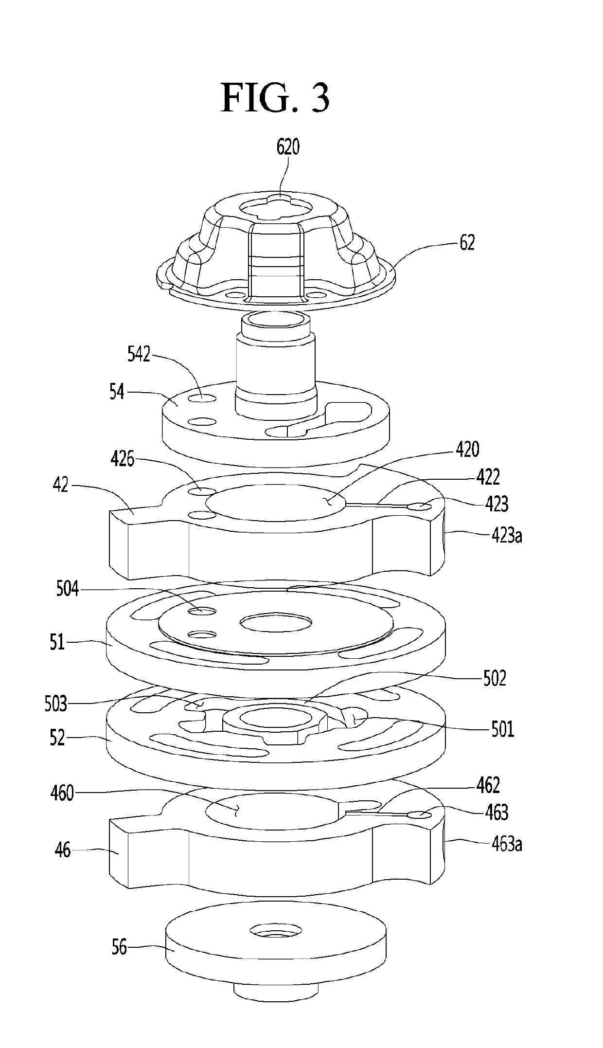
[0037]Referring to FIGS. 1 to 3, a rotary compressor 1 according to the present invention may include a shell 10 forming an internal space, a top cap 11 coupled to the top of the shell 10, and a bottom cap 12 coupled to the bottom of the shell 10.
[0038]The shell 10, for example, may be formed in a cylindrical shape. The shell 10 may have a top opening and a bottom opening.
[0039]A portion of the top cap 11 may be formed in a cylindrical shape and may be inserted in the shell 10 through the top opening of the shell 10.
[0040]A portion of the bottom cap 12 may be formed in a cylindrical shape and may be inserted in the shell 10 through the bottom opening of the shell 10.
[0041]Alternatively, the shell 10 is open at the top or the bottom, but one of them may be closed. In this case, the opening of the shell 10 can be covered by a single cap.
[0042]A plurality of suction pipes 13 and 14 may be connected to the shell 10 and an exhaust pipe 15 may be connected to the top cap 11. The suction p...
second embodiment
[0141]FIG. 6 is an exploded perspective view of an intermediate plate according to the present invention.
[0142]Referring to FIG. 6, an intermediate plate 70 according to the second embodiment of the present invention may include an intermediate plate body 71 and an intermediate plate cover 72. The intermediate plate cover 72 can be fixed to the intermediate plate body 71 while covering a portion of the intermediate plate body 71. The intermediate plate cover 72 can cover the top of the intermediate plate body 71. Rotary shaft holes 715 and 725 through which a rotary shaft can be disposed may be formed in the intermediate plate 70.
[0143]In the embodiment, the intermediate plate body 71 can be understood as the ‘second intermediate plate’ of the first embodiment and the intermediate plate cover 72 can be understood as the ‘first intermediate plate’ of the first embodiment.
[0144]The intermediate plate body 71 may have a first opening 701 and a second opening 703 through which a refrige...
third embodiment
[0150]FIG. 7 is an exploded perspective view of an intermediate plate according to the present invention.
[0151]Referring to FIG. 7, an intermediate plate 80 according to the third embodiment of the present invention may include an intermediate plate body 81 and an intermediate plate cover 82 inserted and fixed in the intermediate plate body 81. An insertion groove 813 in which the intermediate plate cover 82 is inserted may be formed at the intermediate plate body 81. The intermediate plate 80 can be formed by inserting the intermediate plate cover 82 in the insertion groove 813 of the intermediate plate body 81.
[0152]In the embodiment, the intermediate plate body 81 can be understood as the ‘second intermediate plate’ of the first embodiment and the intermediate plate cover 82 can be understood as the ‘first intermediate plate’ of the first embodiment.
[0153]The insertion groove 813 may be formed by recessing a portion of the intermediate plate body 81 downward on the top of the int...
PUM
 Abstract
Description
Claims
Application Information
 - R&D
- Intellectual Property
- Life Sciences
- Materials
- Tech Scout
- Unparalleled Data Quality
- Higher Quality Content
- 60% Fewer Hallucinations
Browse by: Latest US Patents, China's latest patents, Technical Efficacy Thesaurus, Application Domain, Technology Topic, Popular Technical Reports.
© 2025 PatSnap. All rights reserved.Legal|Privacy policy|Modern Slavery Act Transparency Statement|Sitemap|About US| Contact US: help@patsnap.com


