
Power supply monitoring data processing device, power supply monitoring data processing method, and power supply monitoring data processing program

a technology of power supply monitoring and data processing, applied in emergency power supply arrangements, power supply testing, instruments, etc., can solve the problems of excessive fuel consumption, difficult verification of fuel consumption, and unexpected long-term operation of internal combustion power generation devices, etc., to achieve continuous and efficient operation

Inactive Publication Date: 2019-06-20
PANASONIC INTELLECTUAL PROPERTY MANAGEMENT CO LTD
View PDF4 Cites 2 Cited by
  • Summary
  • Abstract
  • Description
  • Claims
  • Application Information

AI Technical Summary

Benefits of technology

The invention provides a way to operate a power source system that uses both a power storage device and an internal combustion power generation device together. This results in a continuous and efficient operation of the system.

Problems solved by technology

When a power failure occurs in a system power source, a backup power source system causes both a storage battery and an internal combustion power generation device to supply a backup power source to a load.
In this case, if the power source is not controlled in accordance with stability of the system power source, the internal combustion power generation device may inevitably operate for an unexpectedly long time.
As a result, excessive amounts of fuel might be consumed.
Many backup power source systems used in developing countries may fail to permit checking of present settings and environment, thus making verification of a fuel consumption difficult.

Method used


Image

  • Power supply monitoring data processing device, power supply monitoring data processing method, and power supply monitoring data processing program
  • Power supply monitoring data processing device, power supply monitoring data processing method, and power supply monitoring data processing program
  • Power supply monitoring data processing device, power supply monitoring data processing method, and power supply monitoring data processing program

Examples


Embodiment Construction

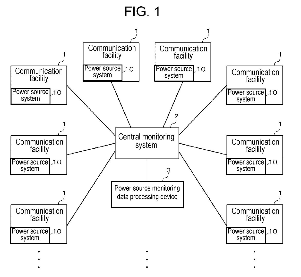
[0018]FIG. 1 illustrates a block diagram of an overall configuration of communication facilities 1, central monitoring system 2, and power source monitoring data processing device 3. Each communication facility 1 has power source system 10. The following description gives an example in which each communication facility 1 serves as a base station device for cellular phones.

[0019]Base station devices for cellular phones installed at many more sites provide higher communication quality. In some vast nations, base station devices are installed at 100,000 or more sites.

[0020]Central monitoring system 2 is a system that remotely monitors power source systems 10 in the plurality of communication facilities 1. For example, central monitoring system 2 may include a plurality of servers. Central monitoring system 2 is connected to power source systems 10 in communication facilities 1 over a network and collects monitoring data from power source systems 10. The network may be the Internet or a...


PUM


Abstract

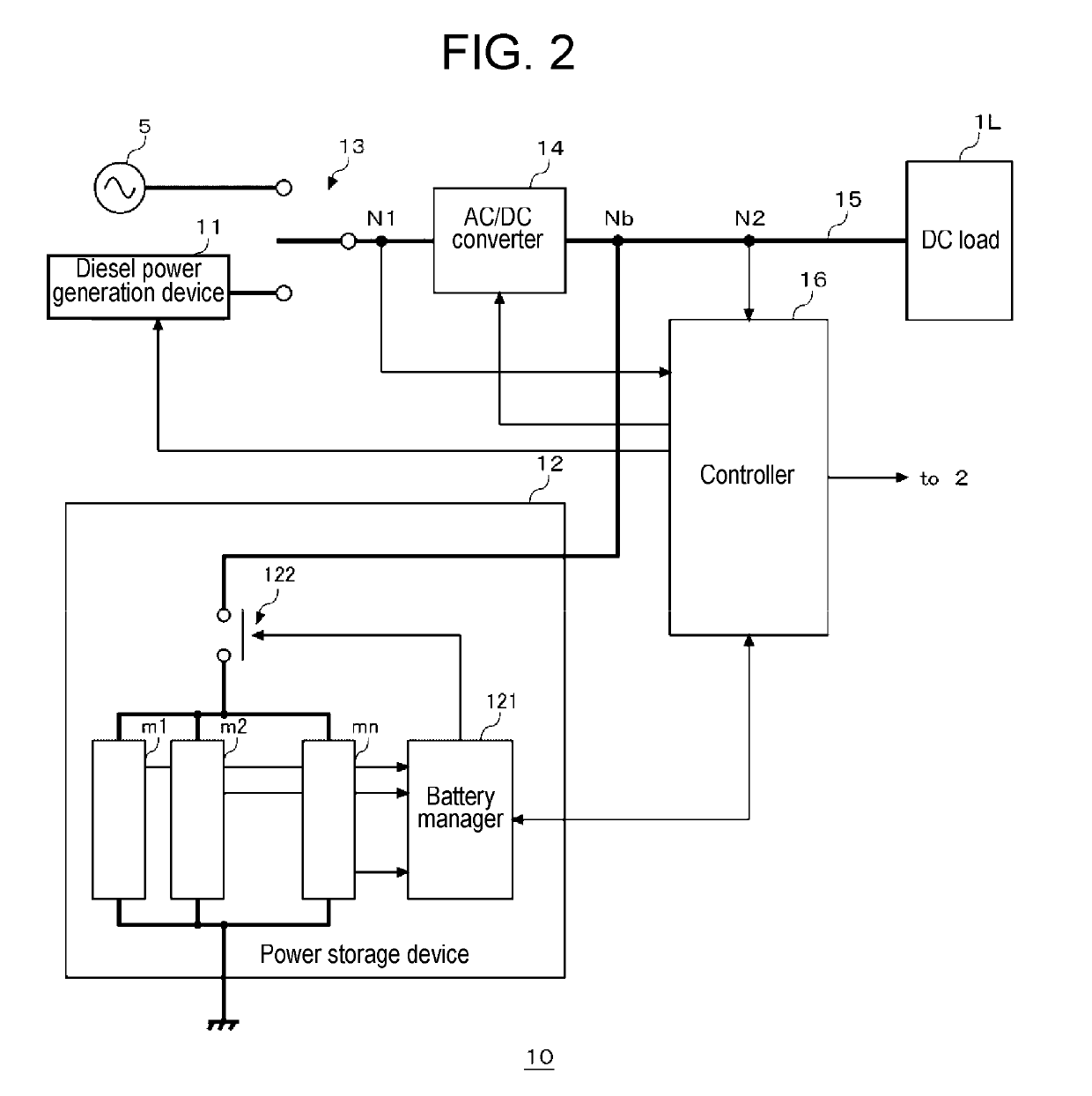
A data acquisition section acquires first data and second data as monitoring data of a power source system that includes a switching section that selectively outputs AC power supplied from a system power source or an internal combustion power generation device, an AC / DC converter that converts the AC power output from the switching section into DC power and outputs the DC power, and a power storage device connected to a DC bus. The first data contains an output voltage and / or an output current of the switching section; the second data contains an output voltage and / or an output current of the power source system. The data processor estimates an operational state of the internal combustion power generation device, based on the first data and the second data, and generates a modification plan for a system configuration and / or a discharge lower limit of the power storage device to shorten an operational time of the internal combustion power generation device.

Description

TECHNICAL FIELD[0001]The present invention relates to a power source monitoring data processing device, a power source monitoring data processing method, and a power source monitoring data processing program, all of which are intended to process monitoring data of a power source system equipped with a backup power storage device.BACKGROUND ART[0002]Electric power conditions in developing countries, including India, Southeast Asian courtiers, and African courtiers, are worse than those in developed countries, including Japan and European countries. Therefore, electric power is often cut off. Power failures in such developing countries happen usually accidentally but sometimes in a planned way. Thus, as a rule, infrastructure installations, such as cellular phone base stations, need to have backup power source systems, which are used upon power failures in system power sources. To provide quality communication services for developing countries, stable facility control for communicatio...

Claims


Application Information

Patent Timeline
IPC IPC(8): H02J3/28H02J13/00H02J9/06G01R31/42
CPCH02J3/28H02J13/0013H02J9/061G01R31/42H02J7/34G01R19/2513H02J13/00006H02J13/00H02J9/06
Inventor HIRANO, JUN
Owner PANASONIC INTELLECTUAL PROPERTY MANAGEMENT CO LTD
Learn More