
Road paver with quick coupling apparatus for the transverse distribution device, and method

Active Publication Date: 2019-06-20
BOMAG
View PDF0 Cites 1 Cited by
  • Summary
  • Abstract
  • Description
  • Claims
  • Application Information

AI Technical Summary

Benefits of technology

The patent text describes a sliding device for a road paver that can be adjusted to different operating situations. The sliding device is made up of two components that move relative to each other. This allows for a sliding distance adjustment to be done easily through a sliding distance adjustment apparatus. Furthermore, the sliding device is equipped with a stop surface that interacts with a stopper on the support housing to prevent rotation of the sliding device. This ensures that the sliding device is locked in the desired position and prevents unwanted movement during operation. Overall, the technology described in the patent text provides a cost-effective and efficient solution for adjusting the sliding distance and ensuring stable operation of the road paver.

Problems solved by technology

So far, the prior art solutions are disadvantageous in that, due to the different requirements with respect to the fastening of the transverse conveyor device, or the transverse distribution device, to the machine frame of the road paver, the transverse distribution device, i.e., its support housing, is implemented with complicated rails for height adjustment and a plurality of threaded and / or pin connections.
When the transverse distribution device needs to be demounted for maintenance works, releasing the several fastening devices and the support in the rails oftentimes requires considerable effort.
Due to the complicated fastening of the respective components to the road paver, this oftentimes necessitates partial demounting of the transverse conveyor device.

Method used


Image

  • Road paver with quick coupling apparatus for the transverse distribution device, and method
  • Road paver with quick coupling apparatus for the transverse distribution device, and method
  • Road paver with quick coupling apparatus for the transverse distribution device, and method

Examples


Embodiment Construction

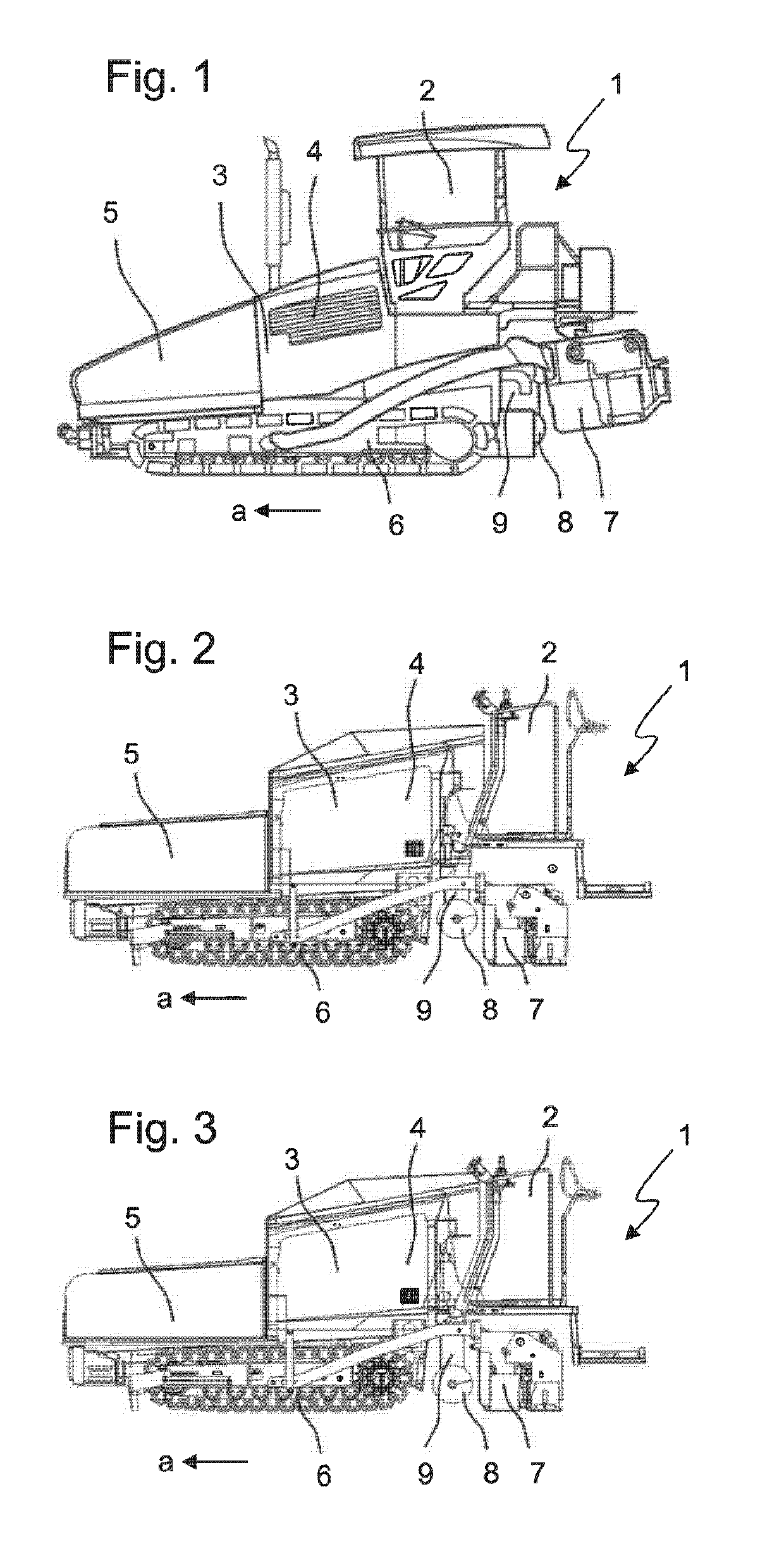
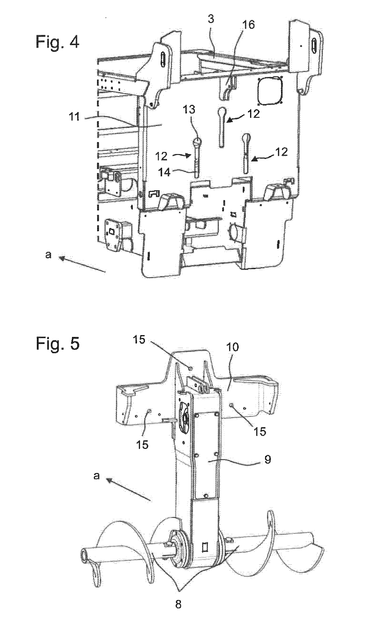
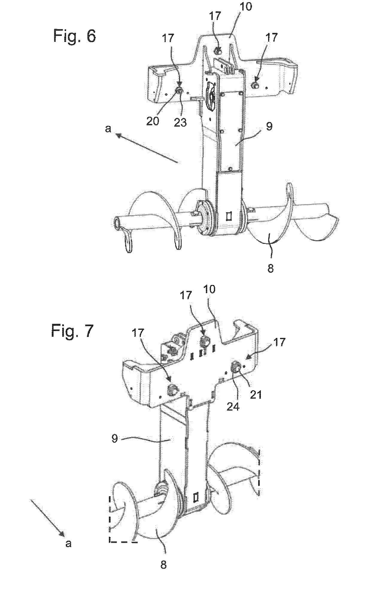
[0047]FIGS. 1 to 3 show exemplary road pavers 1 in which the present invention is used. The road pavers 1 include an operator platform 2 as well as a machine frame 3 with a traveling mechanism 6. In the embodiments shown, the traveling mechanism 6 is depicted with crawler tracks, although wheels might be employed as well. A drive engine 4, for example a diesel combustion engine, is used for propulsion of the road pavers 1. In the front in the working direction a, the road pavers 1 include a material hopper 5 for receiving paving material. The paving material is transported from the material hopper 5 through the so-called tunnel against the working direction a to the rear of the road paver 1, where a transverse distribution device 8 is arranged on a support housing 9. The transverse distribution device 8 distributes the paving material transversely to the working direction a across the full paving width of the road paver 1. The paving screed 7, which screeds the paving material and c...


PUM


Abstract

The present invention relates to a road paver, particularly a small road paver, for paving a subbase layer in a working direction (a), with a machine frame, a traveling mechanism, a material hopper for receiving paving material, a paving screed for smoothing and compacting the paving material, a transverse distribution device for distributing paving material in the working direction (a) in front of the paving screed and transversely to the working direction (a), the transverse distribution device being supported at the machine frame via a support housing, and a height adjustment device for vertical adjustment of the transverse distribution device relative to the machine frame, wherein the support housing is supported at the machine frame such that it is height-adjustable via a quick coupling apparatus, wherein the quick coupling apparatus comprises at least one oblong hole with an expanded insertion portion and a sliding device, wherein the sliding device can be inserted into the oblong hole through the expanded insertion portion, and wherein the sliding device in the inserted state slides in the region of the oblong hole outside the expanded insertion portion during vertical adjustment of the transverse distribution device through the height adjustment device, and wherein the sliding device is supported in a form-closed manner in a direction perpendicular to the height adjustment in this region. Moreover, the invention relates to a method for mounting a transverse distribution device on a road paver.

Description

CROSS-REFERENCE TO RELATED APPLICATION[0001]The present application claims priority under 35 U.S.C. §119 of European Patent Application No. 17002030.9, filed Dec. 14, 2017 and European Patent Application No. 18000032.5, filed Jan. 16, 2018, the disclosures of which are hereby incorporated herein by reference in their entireties.FIELD OF THE INVENTION[0002]The present invention relates to a road paver, particularly a small road paver, for paving a subbase layer in a working direction. Moreover, the present invention also relates to a method for mounting a transverse distribution device on a road paver.BACKGROUND OF THE INVENTION[0003]Road pavers are usually employed for producing the subbase layer of roads or squares. They are self-propelled construction machines usually including a machine frame and a traveling mechanism, for example, crawler tracks or wheels. The central part of a road paver is the paving screed, which extends transversely to the working direction of the road paver...

Claims


Application Information

Patent Timeline
IPC IPC(8): E01C19/48
CPCE01C19/48E01C2301/00E01C19/4853E01C19/12F16B5/0225F16B21/09
Inventor PARRILLA, SAVERIOPEDRIALI, MAURIZIOBALDRATI, FABIO
Owner BOMAG
Learn More