
A method for realizing a through-wall joint capable of adapting to the inclination angle of a mounting surface

A realization method and a technology of the installation surface, which are applied in the direction of electrical components, etc., can solve the problems that the installation wall cannot be completely fitted, and the through-wall joint 1 cannot be effectively fastened, etc., so as to achieve the effect of reliable fastening

Active Publication Date: 2018-12-14
WUHAN HONGXIN TECH DEV CO LTD
View PDF8 Cites 0 Cited by
  • Summary
  • Abstract
  • Description
  • Claims
  • Application Information

AI Technical Summary

Problems solved by technology

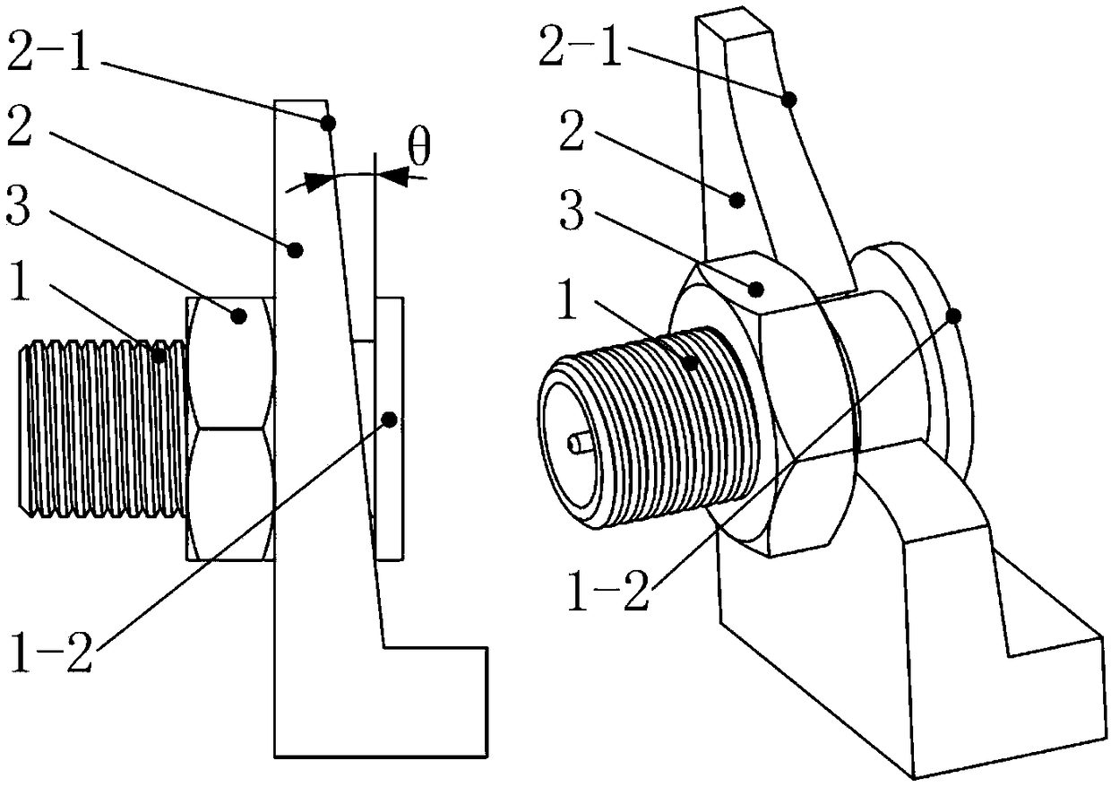
like figure 1 As shown, the equipment casing (the installation wall 2 of the through-wall joint 1) needs to set the draft angle during the mold manufacturing, and the installation surface of the installation wall 2 of the through-wall joint 1 is usually an inclined surface, and there is an inclined installation surface of the installation wall Angle of inclination θ, when the through-wall joint 1 passes through the installation wall 2 and locks the nut 3, the end face of the lock nut 3 and the flange 1 of the through-wall joint 1- At least one of the end faces of 2 cannot completely fit the installation wall 2, so that the through-wall joint 1 cannot be effectively fastened

Method used


Image

  • A method for realizing a through-wall joint capable of adapting to the inclination angle of a mounting surface
  • A method for realizing a through-wall joint capable of adapting to the inclination angle of a mounting surface
  • A method for realizing a through-wall joint capable of adapting to the inclination angle of a mounting surface

Examples


Embodiment Construction

[0016] In order to make the object, technical solution and advantages of the present invention clearer, the present invention will be further described in detail below in conjunction with the accompanying drawings and embodiments. It should be understood that the specific embodiments described here are only used to explain the present invention, not to limit the present invention. In addition, the technical features involved in the various embodiments of the present invention described below can be combined with each other as long as they do not constitute a conflict with each other.

[0017] The technical solution of the present invention will be described in detail below in conjunction with the accompanying drawings and embodiments.

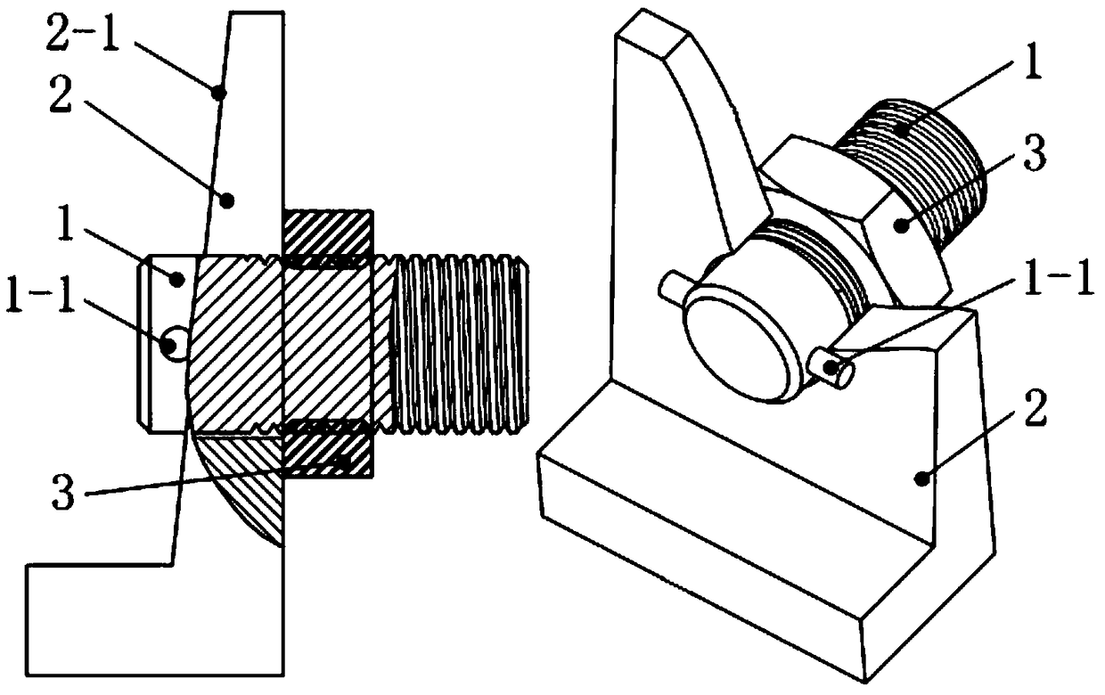
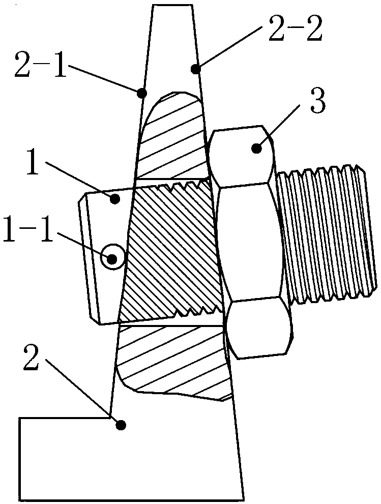
[0018] Such as figure 2 As shown, the flange 1-2 of the through-wall joint 1 in the prior art is replaced by the pin 1-1, the pin 1-1 is installed in the diameter direction of the end face of the through-wall joint 1, and the axis of the pin ...


PUM


Abstract

The invention discloses a method for realizing a through-wall joint capable of adapting to the inclination angle of a mounting surface. The technical points of the invention are as follows: a through-wall joint flange is replaced by a pin, the pin is mounted in the diameter direction of the end face of the through-wall joint, and the pin axis is perpendicular to and intersects with the axis of thethrough-wall joint. When the through-wall joint passes through the mounting wall, the pin of the through-wall joint is pressed against the inclined mounting surface of the mounting wall, the through-wall joint can slightly rotate about the contact line between the through-wall joint and the inclined mounting surface of the mounting wall, and when the through-wall joint is rotated to the directionthat the axis of the through-wall joint is perpendicular to the inclined mounting surface of the other side, the nut and the inclined mounting surface of the other side are in plane contact, and thethrough-wall joint can be reliably fastened. The method provided by the invention has the advantages that the mounting of the through-wall joint is not influenced by the inclination angle of the mounting wall surface, and the through-wall joint can adapt to the mounting of the mounting wall surface at various inclination angles.

Description

technical field [0001] The invention is mainly applied to the design technical field of wall-mounted connectors and wall-mounted joints in electronic equipment, and particularly relates to a method for realizing a wall-mounted joint that can adapt to the inclination angle of the installation surface, and is suitable for wall-mounted connectors, When the installation wall of the through-wall connector is a sloped wall. Background technique [0002] In electronic equipment, the internal and external communication cables of the equipment shell usually need to be transferred and fixed by using wall-mounted connectors. Such as figure 1 As shown, the equipment casing (installation wall 2 of the through-wall joint 1) needs to set the draft angle during mold manufacturing, and the installation surface of the installation wall 2 of the through-wall joint 1 is usually an inclined surface, and there are inclined installation surfaces of the installation wall Angle of inclination θ, w...

Claims


Application Information

Patent Timeline
IPC IPC(8): H02G3/22
CPCH02G3/22
Inventor 吴丛强
Owner WUHAN HONGXIN TECH DEV CO LTD
Learn More