Multilayer coil component
- Summary
- Abstract
- Description
- Claims
- Application Information
AI Technical Summary
Benefits of technology
Problems solved by technology
Method used
Image
Examples
first embodiment
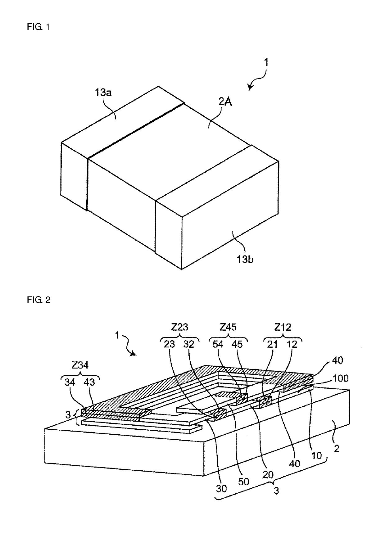
[0051]FIG. 1 is a schematic perspective view illustrating the exterior of a multilayer coil component of a first embodiment. A multilayer coil component 1 includes an element body 2A, a coil 3 (not illustrated in FIG. 1) that is provided inside the element body 2A, and a first outer electrode 13a and a second outer electrode 13b that are provided on the outside of the element body 2A.
[0052]FIG. 2 is a partial schematic perspective view of the multilayer coil component and is for explaining the inside of the element body 2A illustrated in FIG. 1. Therefore, in FIG. 2, for ease of understanding, only an element body 2, which is the part of the element body 2A that is located below the coil 3, is illustrated, and illustration of the first outer electrode 13a and the second outer electrode 13b in FIG. 1 is omitted.
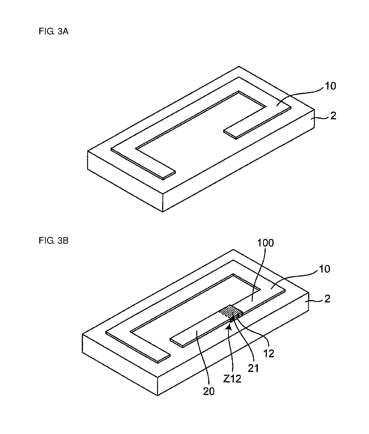
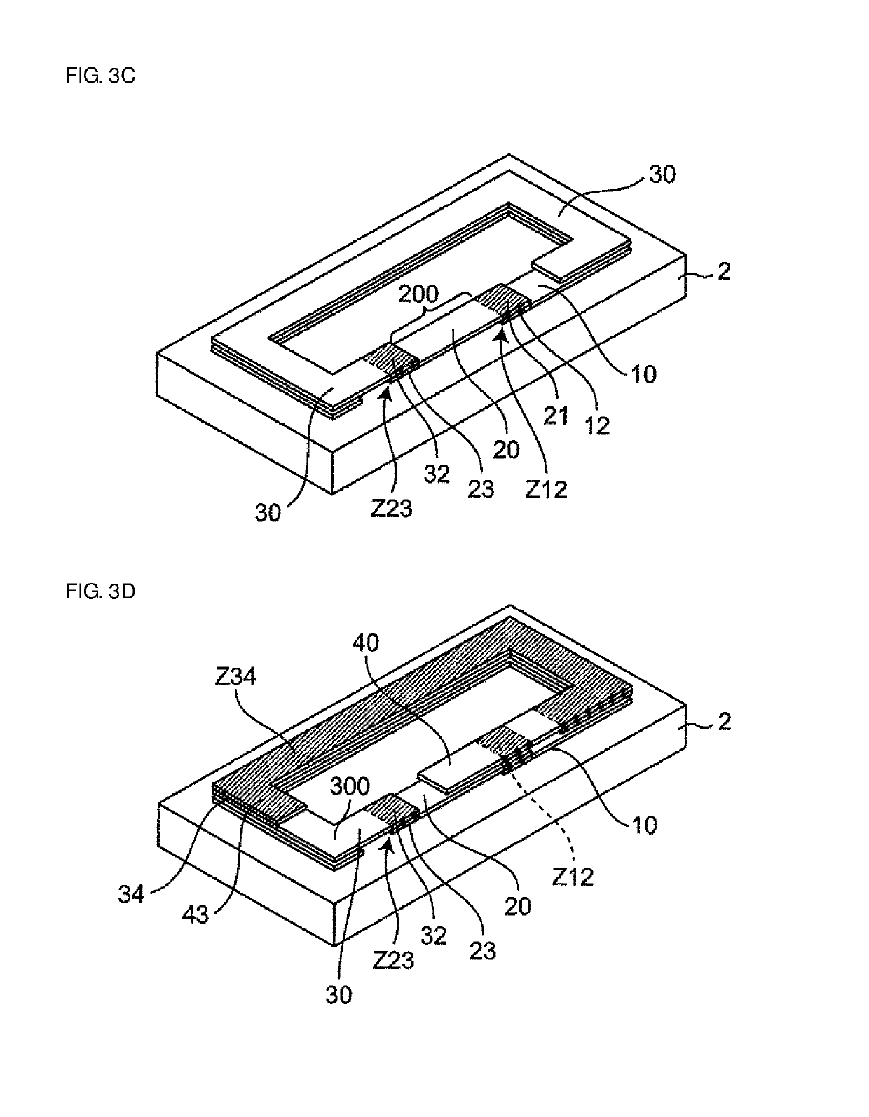
[0053]In FIG. 2, the multilayer coil component 1 includes the element body 2, and the coil 3, which includes a plurality of coil conductors 10, 20, 30, 40, and 50 that are sta...
second embodiment
[0097]FIGS. 5A to 5E are explanatory diagrams, which are seen from above, that are for explaining steps of stacking coil conductors in a second embodiment. FIG. 6 is a schematic diagram of a coil 3a of a multilayer coil component of the second embodiment that is for explaining the connection relationships between a first coil conductor 10a, a second coil conductor 20a, a third coil conductor 30a, a fourth coil conductor 40a, and a fifth coil conductor 50a illustrated in FIGS. 5A to 5E, and in which the coil conductors 10a, 20a, 30a, 40a, and 50a have been extended out in a straight line.
[0098]The second embodiment differs from the first embodiment in terms of the shapes and so forth of the first to fifth coil conductors 10a to 50a of the coil 3a. These differences will be described below.
[0099]Hereafter, the description will focus on points that are different from the first embodiment. The rest of the configuration is the same as in the first embodiment, and parts that are the same ...
third embodiment
[0126]FIGS. 7A to 7E are explanatory diagrams, which are seen from above, that are for explaining steps of stacking coil conductors in a third embodiment. FIG. 8 is a schematic diagram of a coil 3b of a multilayer coil component of the third embodiment that is for explaining the connection relationships between first to fifth coil conductors 10b to 50b illustrated in FIGS. 7A to 7E and in which the first to fifth coil conductors 10b to 50b have been extended out into a straight line.
[0127]The third embodiment differs from the first embodiment and the second embodiment in terms of the shapes of the first to fifth coil conductors 10b to 50b of the coil 3b. In addition, the thickness of a non-contact portion 100b of the first coil conductor 10b is larger than the thicknesses of non-contact portions 200b to 500b of the second to fifth coil conductors 20b to 50b. In addition, the length of a contact region Z34b is larger than the length of the non-contact portion 300b and the length of t...
PUM
 Abstract
Description
Claims
Application Information
 - R&D
- Intellectual Property
- Life Sciences
- Materials
- Tech Scout
- Unparalleled Data Quality
- Higher Quality Content
- 60% Fewer Hallucinations
Browse by: Latest US Patents, China's latest patents, Technical Efficacy Thesaurus, Application Domain, Technology Topic, Popular Technical Reports.
© 2025 PatSnap. All rights reserved.Legal|Privacy policy|Modern Slavery Act Transparency Statement|Sitemap|About US| Contact US: help@patsnap.com


