
Light-sheet microscope with parallelized 3D image acquisition

a microscope and 3d image technology, applied in the field of light-sheet fluorescence microscopy, can solve the problems of negating the speed advantage of parallelized acquisition, reducing the amount of fluorescence light reaching a particular detection plane by the degree, and reducing blur, so as to reduce blur, increase the volumetric image acquisition rate, and prolong the exposure time

Active Publication Date: 2019-06-06
BOARD OF RGT THE UNIV OF TEXAS SYST
View PDF0 Cites 5 Cited by
  • Summary
  • Abstract
  • Description
  • Claims
  • Application Information

AI Technical Summary

Benefits of technology

The patent describes an imaging system that can capture images of a sample quickly and with reduced blurring. This is achieved by using a beam of light that is split into multiple beams, each with lower power than the original beam. The multiple beams are then focused onto the sample in parallel, resulting in increased imaging speed without needing a stronger fluorescence signal. The system can also operate at a slower speed while exposing the sample to lower power, reducing photo-bleaching and damage. Overall, this technology allows for faster and more accurate imaging of samples with reduced blurring.

Problems solved by technology

A major bottle neck in 3D fluorescence microscopy is the serial acquisition of 2D images to from an image volume, which can be prohibitive to capturing images of fast biological processes.
Various implementations exist that can image multiple focal planes simultaneously, however, the amount of fluorescence light reaching a particular detection plane is reduced by the degree of parallelization, with the majority of the light being distributed as useless blur on all other detection planes.
For a sample with limited fluorescence emission, such a scheme consequently requires longer exposure times, which negates the speed advantage of parallelized acquisition.

Method used


Image

  • Light-sheet microscope with parallelized 3D image acquisition
  • Light-sheet microscope with parallelized 3D image acquisition
  • Light-sheet microscope with parallelized 3D image acquisition

Examples


Embodiment Construction

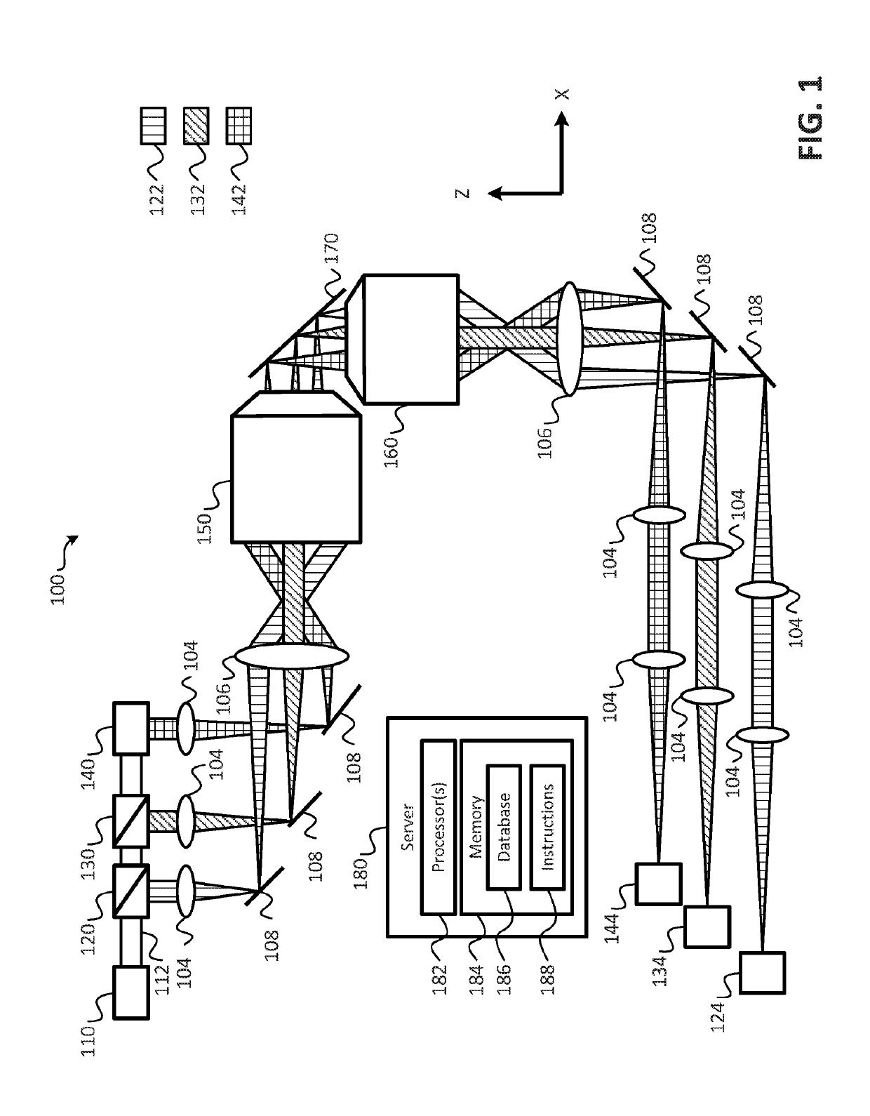
[0049]Referring to FIG. 1, a block diagram of an imaging system that provides parallelized three-dimensional (3D) image acquisition of a sample according to embodiments is shown as an imaging system 100. In an embodiment, the imaging system 100 may operate to perform parallelized 3D image acquisition of a sample. In an embodiment, the sample may be mounted on a coverslip 170. As shown in FIG. 1, the imaging system 100 includes a light source 110, one or more beam splitters (e.g., beam splitters 120, 130), a mirror 140, an illumination objective 150, a detection objective 160, a plurality of cameras 124, 134, 144, a plurality of lenses 104, 106 (e.g., tube lenses), and a plurality of mirrors 108. It is noted that the arrangement of the various components of the imaging system 100 illustrated in FIG. 1 are provided for purposes of illustration, rather than by way of limitation, and that components may be added to, or removed from the imaging system 100 without departing from the scope...


PUM


Abstract

This disclosure includes an imaging system that is configured to image in parallel multiple focal planes in a sample uniquely onto its corresponding detector while simultaneously reducing blur on adjacent image planes. For example, the focal planes can be staggered such that fluorescence detected by a detector for one of the focal planes is not detected, or is detected with significantly reduced intensity, by a detector for another focal plane. This enables the imaging system to increase the volumetric image acquisition rate without requiring a stronger fluorescence signal. Additionally or alternatively, the imaging system may be operated at a slower volumetric image acquisition rate (e.g., that of a conventional microscope) while providing longer exposure times with lower excitation power. This may reduce or delay photo-bleaching (e.g., a photochemical alteration of the dye that causes it to no longer be able to fluoresce), thereby extending the useful life of the sample.

Description

CROSS-REFERENCE TO RELATED APPLICATIONS[0001]This application claims the benefit of U.S. Provisional Patent Application No. 62 / 321,496, filed on Apr. 12, 2016 and entitled “LIGHT-SHEET MICROSCOPE WITH PARALLELIZED 3D IMAGE ACQUISITION,” the contents of which is expressly incorporated herein by reference in its entirety.FIELD OF INVENTION[0002]The present disclosure is generally related to light-sheet fluorescence microscopy (LSFM), and more particularly to parallelization techniques for use in generating images using LSFM techniques.BACKGROUND[0003]A major bottle neck in 3D fluorescence microscopy is the serial acquisition of 2D images to from an image volume, which can be prohibitive to capturing images of fast biological processes. Various implementations exist that can image multiple focal planes simultaneously, however, the amount of fluorescence light reaching a particular detection plane is reduced by the degree of parallelization, with the majority of the light being distribu...

Claims


Application Information

Patent Timeline
IPC IPC(8): G01N21/64G02B21/00
CPCG01N21/6458G02B21/0032G02B21/008G02B21/0076G01N2021/6463G01N2201/061G02B21/16G02B21/367G02B27/1066G02B27/144
Inventor FIOLKA, RETO P.
Owner BOARD OF RGT THE UNIV OF TEXAS SYST
Learn More