
Methods and apparatuses for scheduling service area in drone network environment

a technology of drone network environment and service area, applied in the field of communication network technology using a drone, can solve the problems of reducing the communication quality of terminals at the edge of the service area, affecting the service area, so as to improve network performance efficiency, reduce the transmission opportunity of sensor terminals, and improve the effect of network performance efficiency

Active Publication Date: 2019-05-16
RES & BUSINESS FOUND SUNGKYUNKWAN UNIV
View PDF0 Cites 7 Cited by
  • Summary
  • Abstract
  • Description
  • Claims
  • Application Information

AI Technical Summary

Benefits of technology

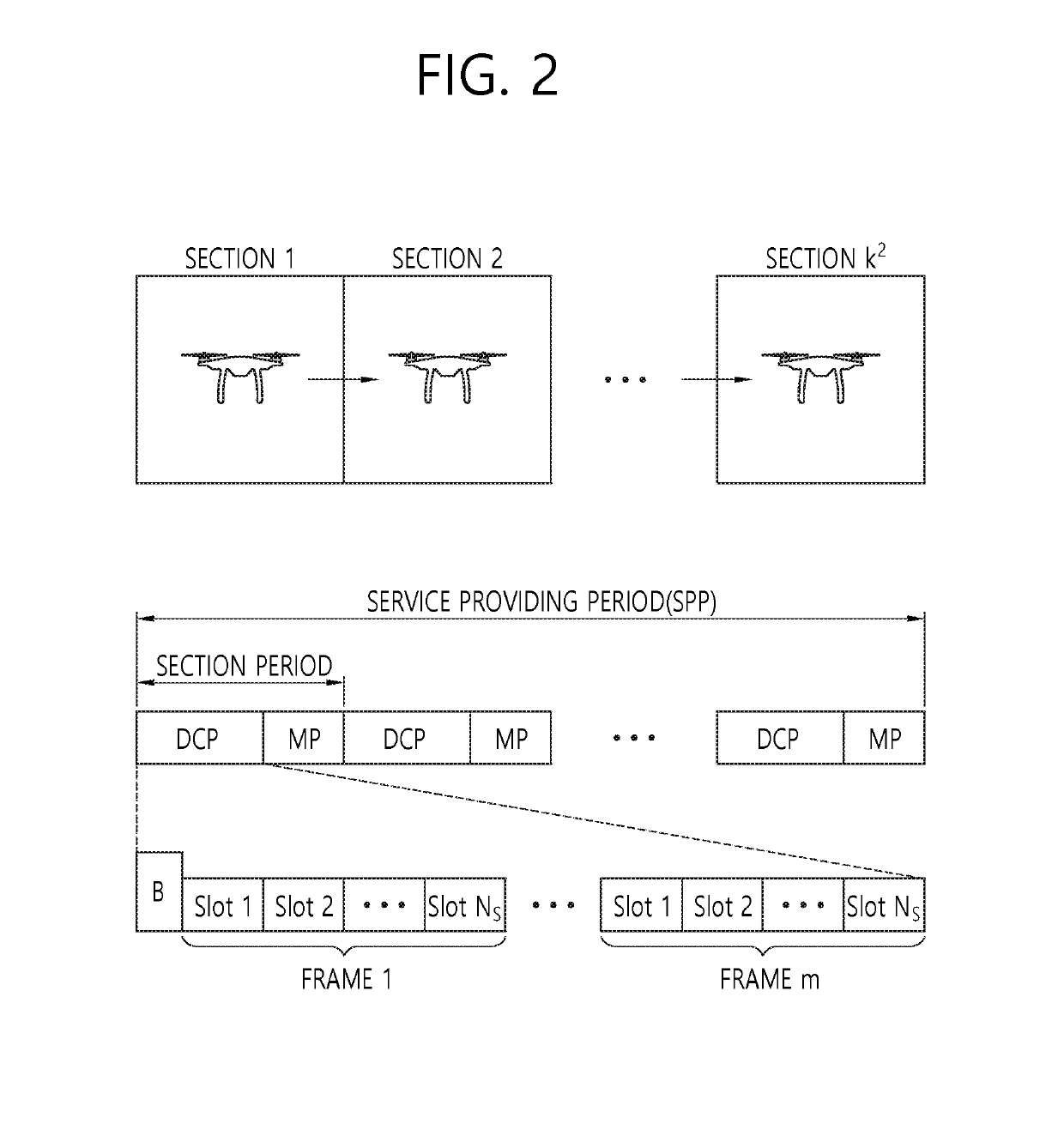
The patent text describes a method for improving communication between a drone and a sensor terminal in a service area. By dividing the service area into multiple sections, the size of each section is reduced, which reduces the distance between the sensor terminal and the drone. This results in an improved channel environment for communication, making the drone more robust against channel errors. The method also enhances energy-efficiency of drone networks by collecting maximum data during the flight time.

Problems solved by technology

Accordingly, it is expected that a wireless communication service using drones in areas where base stations are difficult to install will attract attention.
Considering the mobility of the drones, since the service area to be served by the drones is relatively wide, the terminals at the edge of the service area have a limitation of degradation of the communication quality.
In addition, the drones have a limitation in communicable distance due to the antenna sensitivity and output limit of the transmitted signals.
However, in terms of the transmission opportunity, as the number of sections increases, the traveling time of the drone increases and thus the transmission opportunity of the sensor terminal decreases.
However, there is no scheduling method for dividing a service area into an optimal number of sections, which results in lowered network performance efficiency.

Method used


Image

  • Methods and apparatuses for scheduling service area in drone network environment
  • Methods and apparatuses for scheduling service area in drone network environment
  • Methods and apparatuses for scheduling service area in drone network environment

Examples


Embodiment Construction

[0045]Since the present invention may be modified into various types and may be implemented into various embodiments, specific embodiments will be illustrated in the drawings and described in this disclosure in detail.

[0046]However, the present invention is not limited to a specific implementation type, but should be construed as including all modifications, equivalents, and substitutes involved in the spirit and the technical scope of the present invention.

[0047]The terms such as “a first / the first” and “a second / the second” may be used to describe various components, but the components should not be limited by the terms. The terms are used only in order to distinguish one component from another component. For example, a first component may be named a second component without deviating from the scope of the present invention, and similarly, the second component may be named the first component. The term “and / or” includes a combination of a plurality of related items or any one of a...


PUM


Abstract

Provided is methods and apparatuses for scheduling service area in drone network environment. The method includes calculating a throughput in each section while changing a variable determining the number of sections within a maximum value of the variable and determining a variable, by which the calculated throughput becomes maximum, as an optimal value when a service area of the drone is divided into a plurality of sections, dividing the service area into a plurality of sections according to the determined optimal value and scheduling a service providing period of the divided service area, and communicating with a terminal located in the service area according to the scheduled service providing period. The present invention can enhance the networks throughput and energy-efficiency of drone networks.

Description

CROSS-REFERENCE TO RELATED APPLICATIONS[0001]This application claims priority to Korean Patent Application No. 10-2017-0152234 filed on 15 Nov. 2017 in Korea, the entire contents of which are hereby incorporated by reference in their entirety.BACKGROUND1. Technical Field[0002]The present invention relates to a communication network technology using a drone, and more particularly, to methods and apparatuses for scheduling a service area in a drone network environment.2. Description of Related Art[0003]A communication network technology using drones is as follows. Unmanned Aerial Vehicles (UAVs) or drones are being mainly used as tactical targets in the military field. However, drones have recently been expanding their application fields to the commercial sector. In particular, since drones are able to move without a geographical limitation, drones have an advantage in that they may be quickly deployed to a target area. Technologies for providing wireless communication to a target are...

Claims


Application Information

Patent Timeline
Patent Type & Authority Applications(United States)
IPC IPC(8): H04W72/12G06Q10/06B64C39/02
CPCH04W72/1231G06Q10/06314B64C39/024B64C2201/122B60L11/1809H04B7/18504B60L2240/70B60L2240/72B60L53/68B60L53/67Y02T90/16Y02D30/70Y02T10/72Y02T10/7072Y02T10/70Y02T90/14Y02T90/12B64U2101/20B64U2201/00H04W24/02H04W84/005H04W84/06H04W72/12B60L53/00H04W16/24H04W72/542
Inventor LEE, TAE-JINKIM, YUNMIN
Owner RES & BUSINESS FOUND SUNGKYUNKWAN UNIV
Learn More