Power storage device packaging material

a technology of storage devices and packaging materials, which is applied in the direction of packaging, domestic packaging, synthetic resin layered products, etc., can solve the problems of fine cracks that may more easily develop in the sealant layer, and achieve the improvement of properties necessary for packaging materials, the effect of further reducing or preventing the deterioration of insulation properties after degassing heat sealing

Pending Publication Date: 2019-05-16
TOPPAN PRINTING CO LTD
View PDF11 Cites 2 Cited by
  • Summary
  • Abstract
  • Description
  • Claims
  • Application Information

AI Technical Summary

Benefits of technology

The present invention provides a power storage device packaging material that reduces or prevents defects during the production process, such as heat sealing, and maintains insulation properties after degassing heat sealing. The material includes a sealant layer that is liable to develop defects due to its high fluidity during heat sealing. The invention proposes the use of a propylene-based branched polymer in the sealant layer to reduce or prevent deformation and improve insulation properties. The content of the propylene-based branched polymer in the sealant layer is preferably 1.0 mass % to 50.0 mass % relative to the total mass of the sealant layer. The sealant layer may include more than one layer, and the layer closest to the metal foil layer is preferably the propylene-based branched polymer-containing layer.

Problems solved by technology

However, if the inner layer is made thinner, fine cracks may more easily develop in the sealant layer due to stress during cold forming, and the electrolyte may penetrate into the cracks and easily deteriorate the insulation properties after forming.

Method used


Image

  • Power storage device packaging material
  • Power storage device packaging material
  • Power storage device packaging material

Examples


example 1

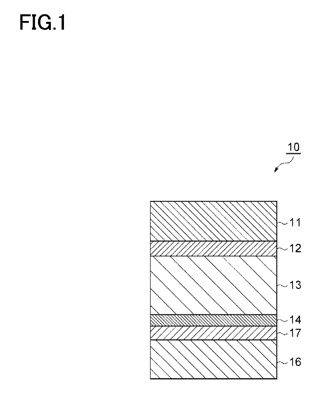
[0268]First, the first and second anticorrosion treatment layers were provided on the metal foil layer through the following procedure. That is, (CL-1) was applied to both surfaces of the metal foil layer by micro gravure coating at a dry coating weight of 70 mg / m2, followed by baking at 200° C. in a drying unit. Next, (CL-2) was applied to the obtained layer by micro gravure coating at a dry coating weight of 20 mg / m2, thereby forming a composite layer of (CL-1) and (CL-2) as first and second anticorrosion treatment layers. The composite layer developed corrosion prevention performance by compounding two materials (CL-1) and (CL-2).

[0269]Next, the first anticorrosion treatment layer side of the metal foil layer provided with the first and second anticorrosion treatment layers was dry-laminated to a substrate layer using a polyurethane-based adhesive (first adhesive layer). The resultant laminate was loaded on an unwinding unit of an extrusion laminator and coextrusion was conducted...

example 2

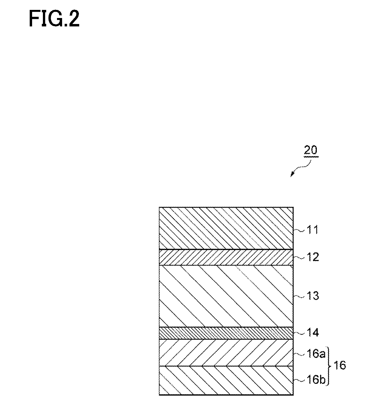
[0271]A packaging material of Example 2 was prepared in the same manner as in Example 1 except that the content of the branched polymer A in the AL side layer (sealant layer 16a) was 3 mass % relative to the total mass of the AL side layer (sealant layer 16a). In the present example, the AL side layer (sealant layer 16a) was the propylene-based branched polymer-containing layer.

example 3

[0272]A packaging material of Example 3 was prepared in the same manner as in Example 1 except that the content of the branched polymer A in the AL side layer (sealant layer 16a) was 10 mass % relative to the total mass of the AL side layer (sealant layer 16a). In the present example, the AL side layer (sealant layer 16a) was the propylene-based branched polymer-containing layer.


PUM

PropertyMeasurementUnit
thicknessaaaaaaaaaa
thicknessaaaaaaaaaa
thicknessaaaaaaaaaa

Abstract

A power storage device packaging material includes at least a substrate layer, a metal foil layer having an anticorrosion treatment layer on one or both sides thereof, and a sealant layer in this order. In the packaging material, the sealant layer includes a propylene-based branched polymer-containing layer that contains a propylene-based branched polymer having branched chains.

Description

CROSS-REFERENCE TO RELATED PATENT APPLICATIONS[0001]This application is a continuation application filed under 35 U.S.C. § 111(a) claiming the benefit under 35 U.S.C. §§ 120 and 365(c) of International Patent Application No. PCT / JP2017 / 020278, filed on May 31, 2017, which is based upon and claims the benefit of priority to Japanese Patent Application No. 2016-111009, filed on Jun. 2, 2016, the disclosures of which are all hereby incorporated herein by reference in their entireties.TECHNICAL FIELD[0002]The present invention relates to a power storage device packaging material.BACKGROUND ART[0003]Known power storage devices include secondary batteries, such as lithium ion batteries, nickel hydride batteries, and lead batteries, and electrochemical capacitors, such as electric double layer capacitors. Due to miniaturization of mobile devices, limitation of installation spaces, or the like, further miniaturization of power storage devices is sought, and thus attention is given to lithiu...

Claims


Application Information

Patent Timeline
Patent Type & Authority Applications(United States)
IPC IPC(8): B32B15/085B32B15/088B32B15/09B32B7/12H01M2/08H01M2/02H01M50/105H01M50/117H01M50/119H01M50/121H01M50/122H01M50/126H01M50/145H01M50/186H01M50/193H01M50/197
CPCB32B15/085B32B15/088B32B15/09B32B7/12H01M2/08H01M2/0287H01M2/0277B32B2255/06B32B2255/20B32B2553/00B32B2307/304B32B2457/10B32B15/08H01G11/78B32B27/08B32B27/32B32B2255/26B32B2307/31B32B2307/714B32B2307/752B32B2439/40Y02E60/10H01M50/124H01M50/1245H01M50/105H01M50/121H01M50/186H01M50/193H01M50/145H01M50/117H01M50/126H01M50/197H01M50/119H01M50/122B32B2457/16B32B2323/10B32B15/20Y02E60/13
Inventor OGIWARA, YUIMAMOTO, JUNYASUZUTA, MASAYOSHI
Owner TOPPAN PRINTING CO LTD
Why Eureka
Try Eureka