Fluorescent probe, method for detecting fluorescence, and method for using fluorescent probe

a fluorescence probe and fluorescent probe technology, applied in the field of fluorescent probes, can solve problems such as the difficulty of observing fluorescence-labeled cells bound to near-infrared fluorescent probes in vitro

Inactive Publication Date: 2019-05-09
NAGOYA UNIVERSITY +1
View PDF0 Cites 1 Cited by
  • Summary
  • Abstract
  • Description
  • Claims
  • Application Information

AI Technical Summary

Benefits of technology

This patent describes a way to use a special probe that includes two different fluorescent dyes that can be excited by different wavelengths of light. This allows for both in vitro and in vivo imaging analysis using existing fluorescence imaging equipment. The fluorescence-labeled cells can also be screened, transplantated into living organisms, and observed as they move around over time. The technical effect of this invention is the ability to perform more accurate and reliable fluorescence imaging analysis in both in vitro and in vivo settings.

Problems solved by technology

Under current circumstances, the fluorescence of the near-infrared fluorescent probe for observation of a living organism cannot be detected using an in vitro fluorescence imaging apparatus such as a fluorescence microscope or a flow cytometer, and it is difficult to observe fluorescence-labeled cells bound to the near-infrared fluorescent probe in vitro.

Method used


Image

  • Fluorescent probe, method for detecting fluorescence, and method for using fluorescent probe
  • Fluorescent probe, method for detecting fluorescence, and method for using fluorescent probe
  • Fluorescent probe, method for detecting fluorescence, and method for using fluorescent probe

Examples


example 1

[0092]Production of Fluorescent Probe

[0093]Production of Complex of Carrier Molecule and Fluorescent Dye a

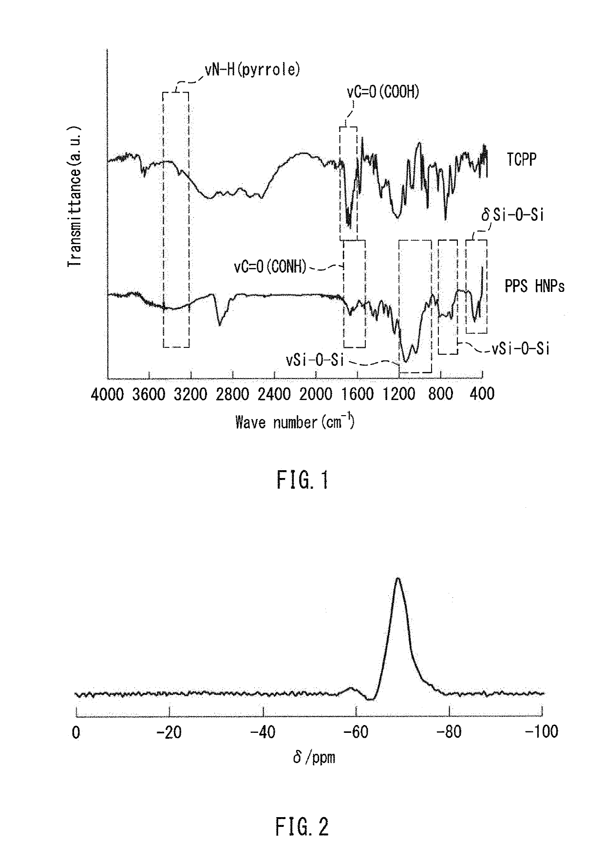
[0094](1) APTES (462 μmol) was added to a DMF solution of TCPP (3.8 mM: 32 mL) obtained by dissolving TCPP in DMF, and then N,N′-dipropylcarbodiimide (480 μmol) and N-hydroxysuccinimide (480 μmol) were added thereto. The resultant mixture was stirred at 50° C. for 24 hours.

[0095](2) Next, 200 μL (porphyrin-silane: 0.75 μmol) of the DMF solution of porphyrin-silane obtained as described above was mixed with 5 μl (0.027 mmol) of MPTMS. To the obtained mixed solution, 500 μL of DMF and 300 μL of an aqueous solution of ammonia (concentration: 28 mass %, pH 11) were added, and a reaction was carried out at 80° C. for 24 hours.

[0096](3) After 24 hours, the product was collected as a precipitate through centrifugation (15000 rpm for 20 minutes). Then, the product was washed with water and ethanol several times, and was finally dispersed in 1 mL of water.

[0097](4) The obtained substance...

example 2

[0102]Production of Fluorescent Probe

[0103]Production of Complex of Carrier Molecule and Fluorescent Dye a

[0104]PPS HNPs was obtained in the same mariner as in Example 1.

[0105]Step of Binding Fluorescent Dye b and Cell Surface Binding Substance to Carrier Molecule

[0106](1) To 1 mL of the aqueous dispersion of the PPS HNPs obtained as described above, 251 μl of an aqueous solution of FA-PEG-Mal (concentration: 2 mg / mL, FA-PEG-Mal: 1.48×10⁻⁴ mmol) and 63 μl of an aqueous solution of ICG-Mal (concentration: 2 mg / mL, 1.48×10⁻⁴ mmol) were added. The resultant mixture was stirred at 30° C. for 3 hours.

[0107](2) After the reaction, the product was collected as a precipitate through centrifugation (15000 rpm for 20 minutes). Then, the product was washed with water several times, and was finally dispersed in 1 mL of water.

[0108](3) The obtained substance was a complex (fluorescent probe) in which the polysiloxane serves as a carrier molecule, the porphyrin serves as a fluorescent dye a, the ...


PUM


Abstract

The present invention relates to a fluorescent probe including a carrier molecule, a fluorescent dye a bound to the carrier molecule, and a fluorescent dye b bound to the carrier molecule in which the excitation wavelengths of the fluorescent dyes a and b are different, and FRET does not occur between the fluorescent dyes a and b. The present invention also relates to a method for detecting fluorescence that includes a step of labeling target cells with the fluorescent probe, and a step of irradiating the target cells labeled with the fluorescent probe with excitation light and observing the fluorescence from the fluorescent probe. The present invention also relates to a method for using a fluorescent probe that includes a step of fluorescently labeling cells with the fluorescent probe, a step of screening the fluorescence-labeled cells using a flow cytometer or a fluorescence microscope, a step of transplanting the screened fluorescence-labeled cells into a living organism, and a step of observing the fluorescence-labeled cells in the living organism using an in vivo fluorescence imaging apparatus.

Description

TECHNICAL FIELD[0001]The present invention relates to a fluorescent probe including two types of fluorescent dyes, a method for detecting fluorescence, and a method for using a fluorescent probe.BACKGROUND ART[0002]In recent years, in vivo fluorescence imaging analysis using animals such as mice has been widely performed in the field of cancer research, embryological research, and the like. The fluorescence imaging analysis is a major technique for analyzing information about positions at which cells such as stem cells including iPS cells, ES cells, and the like and disease-related cells including cancer cells, cirrhotic cells, and the like differentiate, grow, and metastasize after being transplanted into mice. Under current circumstances, only methods using the fluorescence imaging analysis can be used to observe the progression of transplanted cells, particularly with animals such as mice that are still alive, and such methods are regarded as particularly important analysis metho...

Claims


Application Information

Patent Timeline
IPC IPC(8): G01N21/64G01N15/14G01N33/533
CPCG01N21/6428G01N15/14G01N33/533G01N2021/6419G01N2021/6439G01N33/582G01N2021/6441C12Q1/02G01N33/48G01N21/64G01N21/78G01N33/53
Inventor HAYASHI, KOICHIROSAKAMOTO, WATARUYOGO, TOSHINOBUMARUOKA, HIROKI
Owner NAGOYA UNIVERSITY
Why Eureka
Try Eureka