Loudspeaker

Active Publication Date: 2019-04-25
GP ACOUSTICS INT
View PDF6 Cites 0 Cited by
  • Summary
  • Abstract
  • Description
  • Claims
  • Application Information

AI Technical Summary

Benefits of technology

The present invention provides a loudspeaker design that reduces the impact of a resonating space on the driver's response. This is achieved by placing a sound-absorbing material in the space, which dampens its effect. The space is designed to have a quarter-wave resonant frequency that is below the driver's passband, which minimizes its impact. The sound-absorbent material is preferably contained along one edge of the space, leaving an air space adjacent to the voice coil and allowing it to move freely. The invention takes a different approach to reducing the effect of the space, which has resulted in a quieter and more accurate sound produced by the loudspeaker.

Problems solved by technology

However, it defines a generally cylindrical channel 44 around the high-frequency unit 27 which allows some unwanted acoustic resonances to take place, causing irregularities in the high frequency response.
As a result, its stiffness varies strongly with displacement thereby causing harmonic distortion and limiting the maximum sound pressure level of the midrange driver.

Method used


Image

  • Loudspeaker
  • Loudspeaker
  • Loudspeaker

Examples


Embodiment Construction

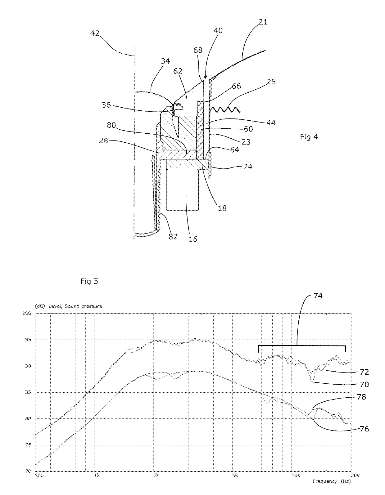
[0029]FIG. 4 shows a first embodiment of the invention. This shares several features with the arrangement of FIG. 2, and like reference numerals are used to denote like parts. The embodiment differs from the arrangement of FIG. 2 in that an annular sleeve of sound-absorbent material 60 in the form of acoustic foam has been fitted around the tweeter unit. This sits in the space between the outer trim 62 of the tweeter unit and the voice coil former 23 of the midrange unit, and effectively lines one side of the annular channel 44 from its deepest point 64 up to a point 66 just behind a ledge 68 of the outer trim 62. The ledge 68 thus conceals the sound-absorbent material 60 from view.

[0030]Sound vibrations entering into the annular channel 44 will therefore be damped, and thus will have a reduced effect on the loudspeaker response. FIG. 5 illustrates measurements comparing the tweeter according to FIG. 2 but with a rigid card sleeve in the annular space 44 (line 70), and the tweeter o...


PUM


Abstract

Sound emanating from the high-frequency diaphragm of a coaxial speaker will diffract into the annular gap between the tweeter unit and the midrange cone. This results in response irregularities. We therefore disclose a loudspeaker, comprising first and second drivers located substantially coaxially with the first driver located centrally and the second driver located concentrically around the first driver, the loudspeaker being bounded at its radially outer side for at least part of its extent by the voice coil former of the second driver and including a spacing between the outermost extent of the first driver and the innermost extent of the second driver thus defining an annular space, the annular space containing a sound-absorbent material. By placing the sound-absorbing material in the annular space, the resonances within this space are damped, thus alleviating their effect. The annular space can have a lower resonant frequency that is below the passband of the first driver. Essentially, instead of minimising the effect of the annular gap by reducing its size and seeking to seal its outer opening, we propose to enlarge the space so that the fundamental resonant frequency it exhibits drops out of the passband of the high-frequency driver and hence out of the frequency range of interest. This both prevents the fundamental frequency of the cavity from being excited, and also allows sufficient room within the space to accommodate a sound-absorbent material to absorb these undesirable resonances.

Description

FIELD OF THE INVENTION[0001]The present invention relates to co-axial loudspeakers.BACKGROUND ART[0002]Co-axial loudspeakers are designed with a high frequency drive unit positioned at or adjacent to the neck of the diaphragm of a low frequency drive unit, as shown in U.S. Pat. No. 5,548,657 and FIG. 1 of the accompanying drawings. As a result, the apparent sound source or acoustic centre of the high frequency drive unit is substantially co-incident with the apparent sound source or acoustic centre of the low frequency drive unit. With the high frequency drive unit positioned adjacent to the neck of the low frequency diaphragm, the form of the low frequency diaphragm imposes its directivity (if any) upon the radiation pattern or directivity of the high frequency unit. Consequently at frequencies at which both drive units contribute significant sound output, both drive units have substantially similar patterns of radiation or directivity. As a result the relative sound contributions ...

Claims


Application Information

Patent Timeline
IPC IPC(8): H04R9/06H04R9/02H04R7/04H04R1/02
CPCH04R9/063H04R9/025H04R7/04H04R1/025H04R9/02H04R9/06H04R2400/11H04R1/24H04R1/2826H04R1/2857H04R1/2869H04R5/02H04R9/04H04R2400/13
Inventor DODD, MARK ALEXANDEROCLEE-BROWN, JACK ANTHONYSPEAR, CHRISTOPHER
Owner GP ACOUSTICS INT
Why Eureka
Try Eureka