
Filter for hight pressure device

Inactive Publication Date: 2011-04-07
GOROZIDIS SIMON
View PDF1 Cites 10 Cited by
  • Summary
  • Abstract
  • Description
  • Claims
  • Application Information

AI Technical Summary

Benefits of technology

[0052]wherein the compartments are in air/fluid communication about the mounting structure such that compressed air entering the inlet port is directed to flow circumferentially about the mounting structure and between the compartments, and thereafter through the filter medium and about the column structure so as to increase the air path such that moisture from the compressed air is substantially removed without substantially destroying the paper medium.
[0053]The filter device can include a releasable holding means mountable on or over the waistband portions of the upper and lower bodies to help maintain the upper and lower bodies of the housing in an air tight condition. The releasable holding means can include a locking system wherein at least a portion of the waistband of the bodies and the holding means comprise complementary mating components that releasably join/engage the upper and lower bodies.
[0054]The upper and lower body elements can be frusto-conical shaped to assist formation of circuitous air/f

Problems solved by technology

If water is not removed from a spray-painting system, there is a tendency for the air passages to become blocked with water.
This water can reach the mechanical drive components of the air tools, which prevent their operation and may be very expensive to repair.
Further, in practice it is found that during spraying, the compressor motor gets hot and water vapour in the compressed air condenses into the compressed air tank.
This may result in ‘spitting’ of moisture at the point of application wherein the moisture becomes embedded in the paint work.
The presence of moisture is also known to affect the resultant colour of a paint applied.
A blemished pain work cannot be rectified by simply painting over the blemished work.
During the painting process, orange peel, fisheyes, blistering, running, and other imperfections in the coating can be cause for rejection and may result in scrapping the body part.
The consequences of paint surfaces which do not meet the required minimum standards is very costly.
The overall costs associated with painting are very large.
Failure to achieve the required quality and luminosity in the paint surface adds greatly to the overall cost.
A great deal of effort and expense is invested in painting, much of which is was

Method used


Image

  • Filter for hight pressure device
  • Filter for hight pressure device
  • Filter for hight pressure device

Examples


Example

DETAILED DESCRIPTION OF THE PREFERRED EMBODIMENTS WITH RESPECT TO THE ACCOMPANYING DRAWINGS

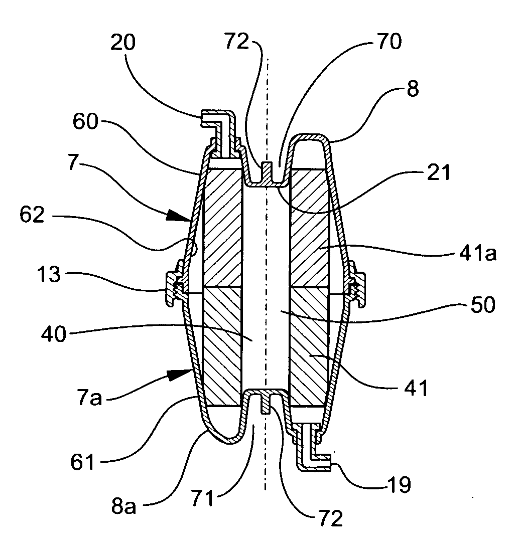
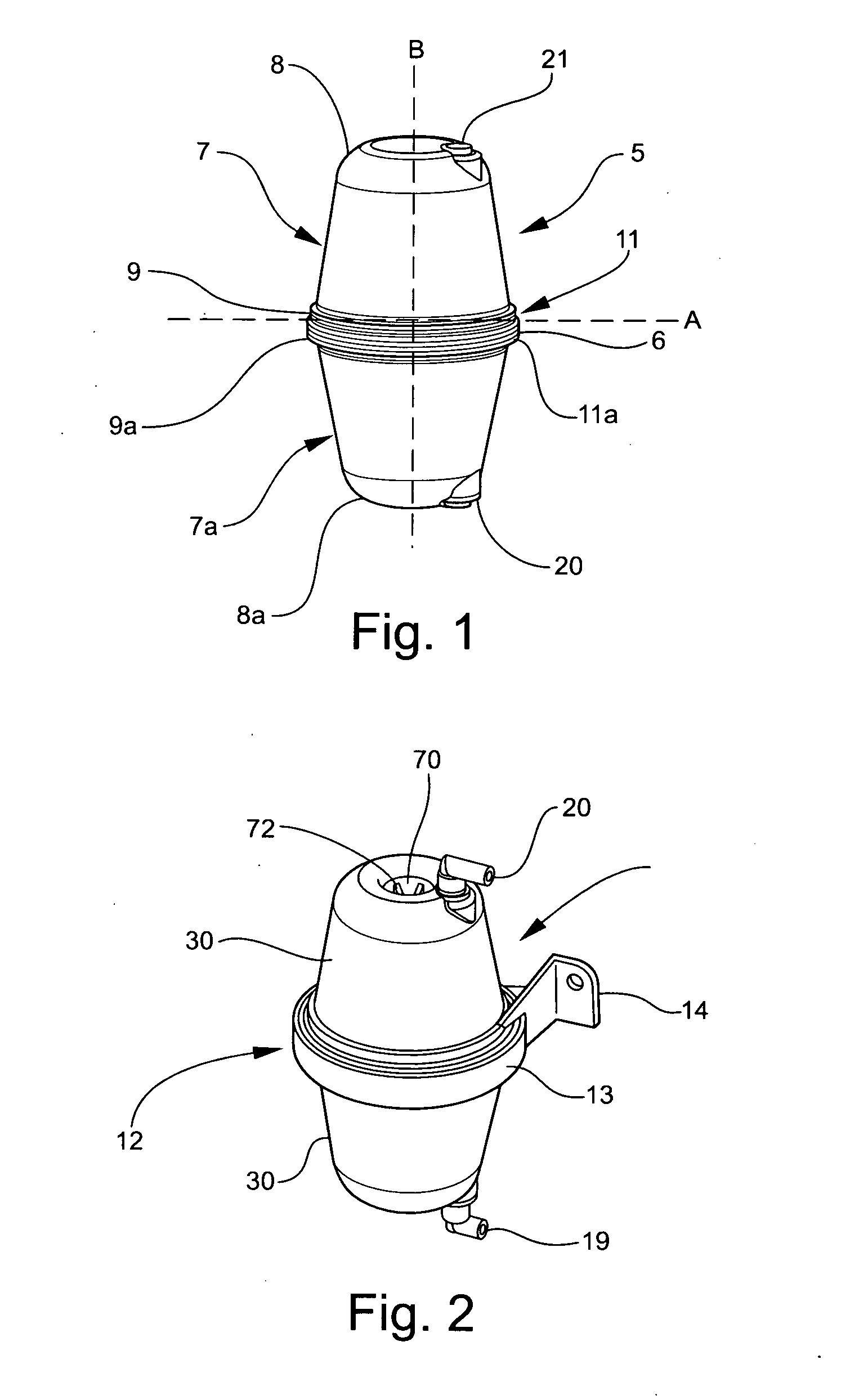
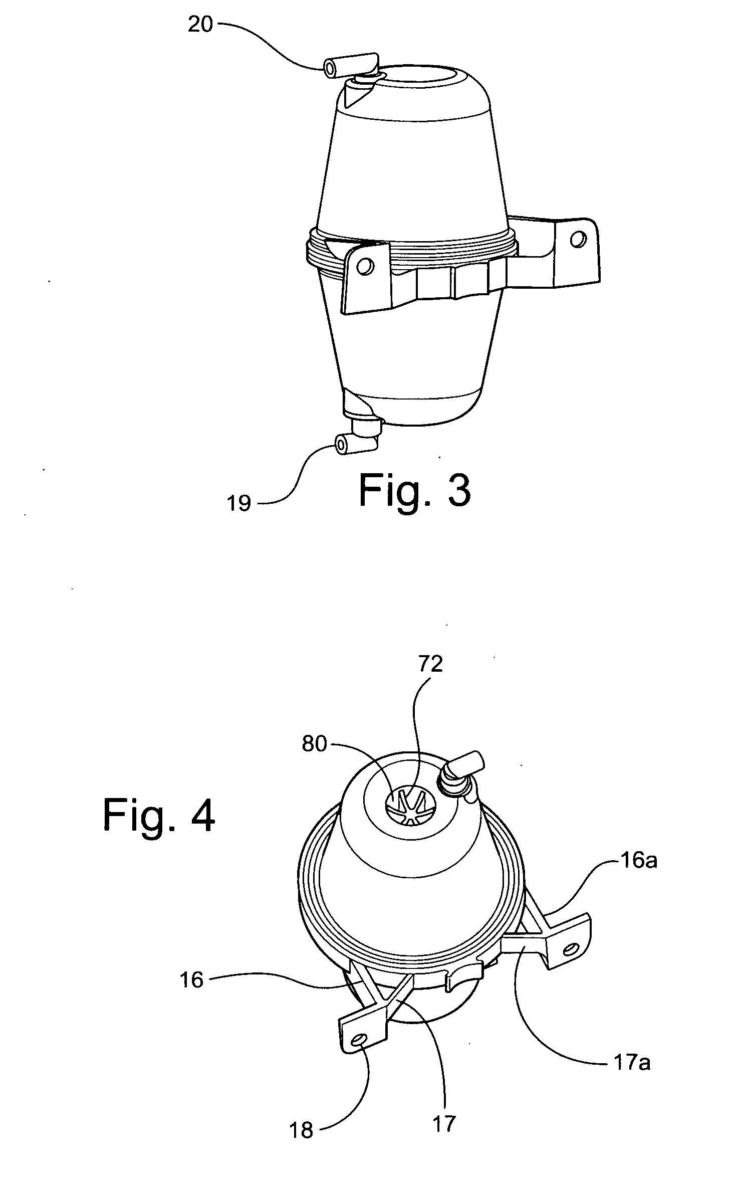
[0064]Referring to the drawings, there is shown a filter device 5 adapted for installing between an air compressor (not shown) and a spray paint gun (not shown) to substantially remove moisture and particulate matter in a compressed air stream prior to application of paint or the like to a vehicle body or other substrate. As shown in FIG. 1 the filter device 5 includes a shaped housing 6 being substantially symmetrical about horizontal line A and vertical line B. The housing comprises an upper body element 7 and a lower body element 7a. The bodies are substantially frusto-conical in shape having a narrow collar end 8 and 8a and waistbands 9 and 9a interconnected by a wall structure 30, each body defining an internal chamber 22 (see FIG. 5). The collars 8 and 8a have closed ends apart from inlet 20 and outlet 21 located in shoulder potions of respective ends.

[0065]In FIG. 1 the upper and lower ...


PUM

PropertyMeasurementUnit
Pressureaaaaaaaaaa
Pressureaaaaaaaaaa
Flow rateaaaaaaaaaa

Abstract

A filter device for substantially minimising moisture and particulate matter in a stream of compressed air or other fluid

Description

[0001]This application claims priority based upon previously filed Australian Patent Application No. 2009222622 filed on 7 Oct. 2009, the contents of which are hereby incorporated by reference.FIELD OF THE INVENTION[0002]The present invention relates to a filter for separating moisture and particulate matter from a stream of high pressure air / fluid. In particular the present invention relates to an air filter for a spray painting assembly, which substantially removes liquid and particulate matter from a stream of compressed air.BACKGROUND OF INVENTION[0003]Spray painting is a painting technique where a device sprays a liquid coating substance such as paint, ink, or varnish through the air onto a surface. Typically paint is changed into a mist or aerosol, in order to apply a coating onto an object or surface.[0004]Most spray painting is performed with the use of a spray gun. A spray gun combines the coating (paint) and compressed air from a separate air compressor in order to atomize...

Claims


Application Information

Patent Timeline
IPC IPC(8): B01D45/16
CPCB05B15/008B05B7/2405B05B15/40
Inventor GOROZIDIS, SIMON
Owner GOROZIDIS SIMON
Learn More