Feeder system

Active Publication Date: 2019-05-14
FOSECO INT LTD
View PDF44 Cites 1 Cited by
  • Summary
  • Abstract
  • Description
  • Claims
  • Application Information

AI Technical Summary

Benefits of technology

The present invention relates to a feeder system for metal casting operations utilizing feeder sleeves. The technical effects of the invention include improved stability of the mould and reduced imperfections in the final casting, as well as a process for preparing the mould. The feeder system includes collapsible feeder elements that protect the feeder sleeve from damage during the moulding process. The invention also addresses the issue of sleeve breakage during high pressure moulding, which can occur when using traditional feeder sleeves.

Problems solved by technology

However, as the metal solidifies it shrinks, resulting in shrinkage cavities which in turn result in unacceptable imperfections in the final casting.
The application of the moulding sand and subsequent high pressures may cause damage and breakage of the feeder sleeve, especially if the feeder sleeve is in direct contact with the pattern plate prior to ram up, and with increasing casting complexity and productivity requirements, there is a need for more dimensionally stable moulds and consequently, a tendency towards higher ramming pressures and resulting sleeve breakages.
The feeder sleeve (102) is in direct contact with the pattern (122), which can be detrimental when an exothermic sleeve is employed since it can result in a poor surface finish, localised contamination of the casting surface and even sub-surface casting defects.
This is unsatisfactory in terms of knock-off and the space taken up by the feeder system on the pattern.
The retaining elements will build up in the moulding sand over time and thereby contaminate it.
This is particularly troublesome where the retaining elements are made from exothermic material since they may react creating small explosive defects.
Certain grades of ductile iron and particular casting configurations may adversely influence the effectiveness of feed performance through the neck of certain metal feeder elements.
Additionally, certain moulding lines or casting configurations may result in over compression (collapsing of the feeder element or telescoping of the feeder system) resulting in the base of the sleeve being in close proximity to the casting surface separated by only a thin layer of sand.
Hence, the high compression pressure causes relative movement between the feeder sleeve and the tubular body rather than uncontrolled breakage of the feeder sleeve that may result in defects in the casting.
A sharp point can pierce the feeder sleeve material and may gouge out a channel during ram-up.
Feeder sleeve material is not generally strong enough to withstand moulding pressures at small thickness, whereas a thicker tubular body requires a wider cut-out in the sidewall and therefore increases the size (and associated cost) of the feeder system as a whole.
Additionally, a tubular body comprising feeder sleeve material may also cause poor surface finish and defects where it is in contact with the casting.
However, care must be taken to ensure that the system is not closed; there is a risk that moulding sand would penetrate into the feeder sleeve through any gaps between the edge of tubular body and the feeder sleeve.
Neither is its mode of manufacture particularly limited, it may be manufactured for example using either the vacuum-forming process or core-shot method.
This movement and contact of the roof with the pin may cause small fragments of sleeve to break off and fall into the casting cavity, resulting in poor casting surface finish or localised contamination of the casting surface.

Method used


Image

  • Feeder system
  • Feeder system
  • Feeder system

Examples


Embodiment Construction

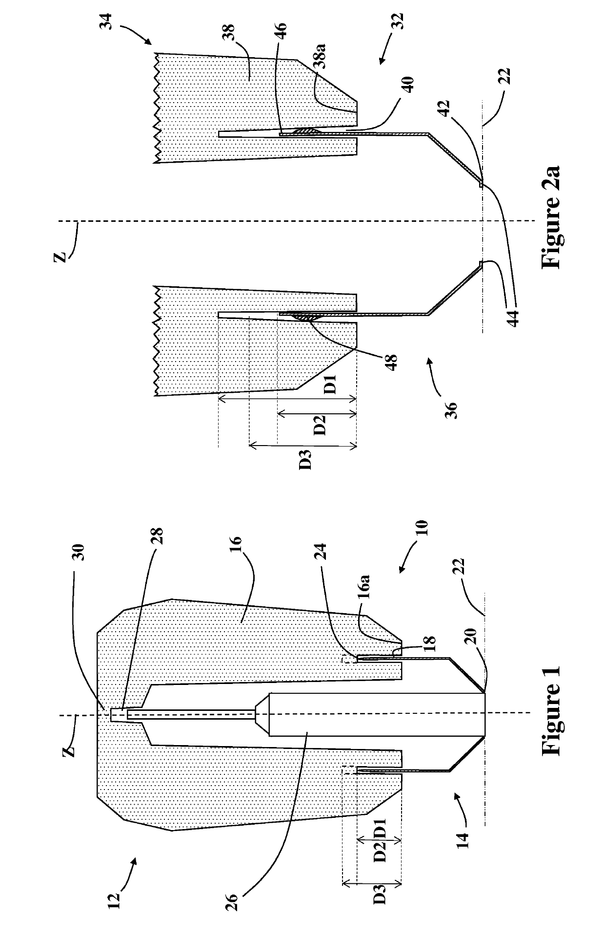
[0079]Referring to FIG. 1 there is shown a feeder system 10 comprising a feeder sleeve 12 having a strength of 8-12 kN mounted on a tubular body 14. The feeder sleeve 12 has a continuous sidewall 16 which extends generally around a longitudinal axis Z; the sidewall 16 defines a cavity for receiving molten metal in use. The sidewall has a base 16a from which a groove 18 having parallel sides extends to a depth D1. The groove 18 is separate from the cavity.

[0080]The tubular body 14 is pressed from sheet steel and defines an open bore therethough (the bore axis lies along the longitudinal axis Z). The tubular body 14 tapers at its end away from the feeder sleeve to form a feeder neck 20 in contact with a moulding pattern plate 22. The opposite end 24 of the tubular body is sharpened to form a circular blade that projects into the groove 18 and is in contact with the feeder sleeve 12. The tubular body 14 projects to the full depth of the groove (D2=D1). On ram-up the sharpened end 24 of...


PUM


Abstract

A feeder system for metal casting comprising a feeder sleeve mounted on a tubular body. The feeder sleeve has a first end and a second end and a longitudinal axis extending generally between said first and second ends. The feeder sleeve comprises a continuous sidewall that extends generally around the longitudinal axis that defines a cavity for receiving liquid metal during casting and the sidewall has a base at the first end of the feeder sleeve. The tubular body defines an open bore therethrough for connecting the cavity to the casting in use. The feeder sleeve comprises at least one cut-out that extends into the sidewall from the base to a first depth and the tubular body projects into the cut-out to a second depth, the tubular body having at least one abrading region in contact with a surface of the feeder sleeve within the cut-out. The second depth is equal to or less than the first depth so that upon application of a force in use the abrading region abrades the surface of the feeder sleeve with which it is in contact such that the tubular body is pushed towards the second end. The invention also resides in a feeder sleeve for use in the system and a process for preparing a casting mold employing the system.

Description

[0001]This application is the U.S. national phase of International Application No. PCT / GB2015 / 052529 filed Sep. 2, 2015, which designated the U.S., the entire content is hereby incorporated by reference.TECHNICAL FIELD[0002]The present invention relates to a feeder system for use in metal casting operations utilising casting moulds, a feeder sleeve for use in the feeder system and a process for preparing a mould comprising the feeder system.BACKGROUND AND SUMMARY[0003]In a typical casting process, molten metal is poured into a pre-formed mould cavity which defines the shape of the casting. However, as the metal solidifies it shrinks, resulting in shrinkage cavities which in turn result in unacceptable imperfections in the final casting. This is a well known problem in the casting industry and is addressed by the use of feeder sleeves or risers which are integrated into the mould, either during mould formation by applying them to a pattern plate, or later by inserting a sleeve into a...

Claims


Application Information

Patent Timeline
IPC IPC(8): B22C9/08
CPCB22C9/084B22C9/088
Inventor VOLKS, CHRISTOF
Owner FOSECO INT LTD
Why Eureka
Try Eureka