
Optical phase retrieval systems using color-multiplexed illumination

Active Publication Date: 2019-04-11
RGT UNIV OF CALIFORNIA
View PDF0 Cites 6 Cited by
  • Summary
  • Abstract
  • Description
  • Claims
  • Application Information

AI Technical Summary

Benefits of technology

The present patent describes a technique for single-shot phase imaging in microscopy that can recover both amplitude and phase from a single color image using minimal hardware modifications. This technique is compatible with most existing microscope hardware and can measure geometric quantities about individual cells, segment cells accurately, and synthesize other types of phase images. It is advantageous because it can achieve high-speed camera-limited frame-rates and can be used in many biomedical applications without the need for chemical staining. The hardware requirements of the technique are flexible, portable, and affordable, providing minimal trade-offs between speed and accuracy.

Problems solved by technology

The complex optical field at a given point can be described by the amplitude and phase of this signal; however, the phase information of the incident wavefront is lost during the integration cycle of a digital imaging sensor.
This method is inherently not quantitative, as it relies on interference of an object with part of its own frequency spectrum and does not completely decouple phase and amplitude, although inversion methods have been proposed.
However, the limited phase bandwidth of these systems is problematic for quantitative phase imaging.
These methods can be very problematic due their expensive and complicated hardware setups, as well as their sensitivity to misalignment and vibrations, making them poorly suited for practical usage for clinical studies.
A similar, viable single-shot alternative, Color TIE, combines techniques of chromatic dispersion with a phase retrieval method using the Transport of Intensity equation, but requires coherent illumination, restricting it's resolution to half of phase imaging methods using partially coherent illumination.
While DPC strikes a favorable balance between resolution, hardware cost, and imaging rate, it is not a single-shot method, and requires a programmable illumination source such as an LED array to achieve real-time frame-rates.

Method used


Image

  • Optical phase retrieval systems using color-multiplexed illumination
  • Optical phase retrieval systems using color-multiplexed illumination
  • Optical phase retrieval systems using color-multiplexed illumination

Examples


Embodiment Construction

[0036]1. Hardware Description

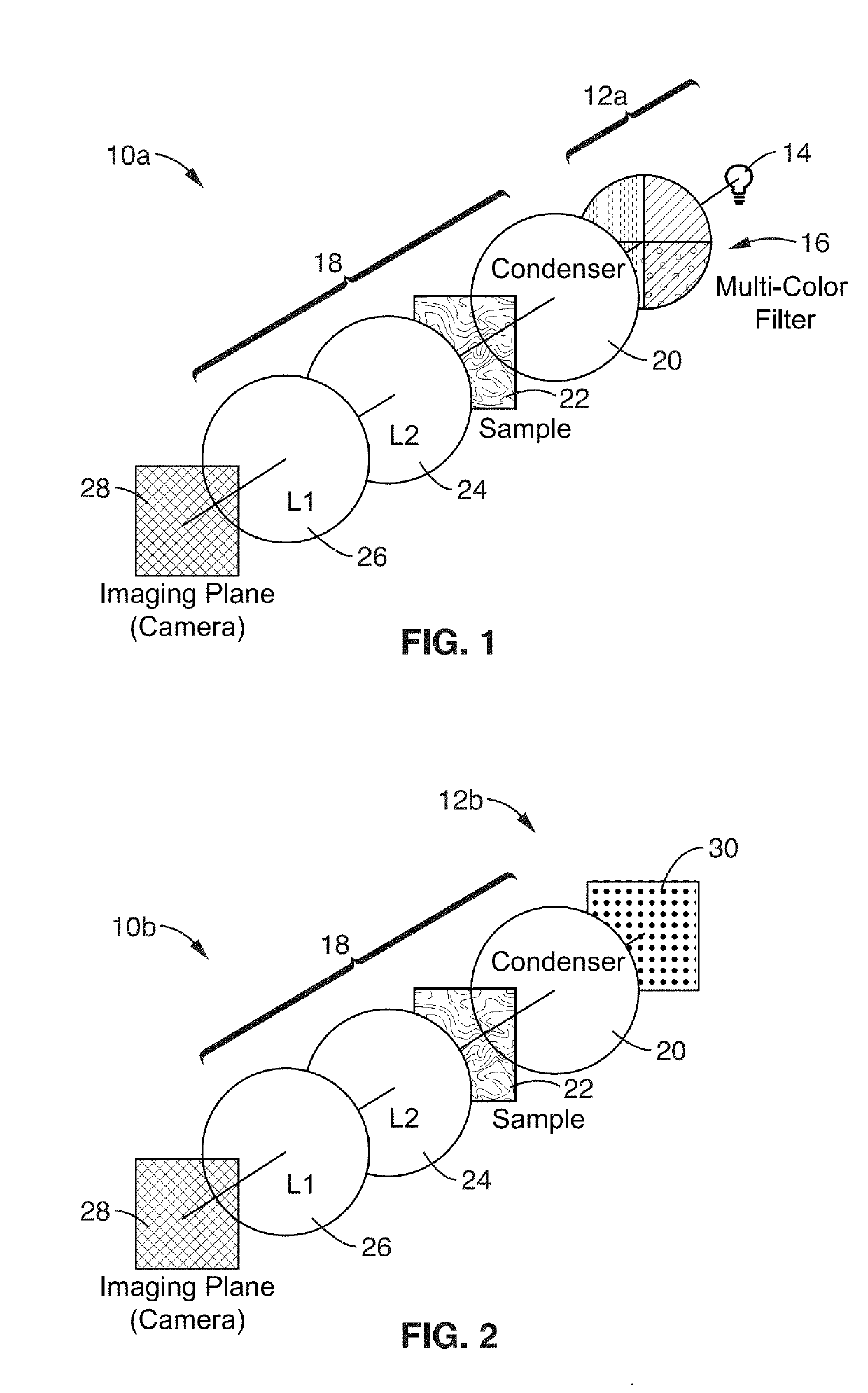
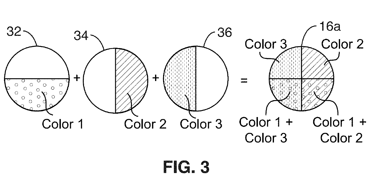
[0037]The general hardware components for practicing the methods of the present description are: 1) a color-encoded illumination source (either from a programmable source or static filter); 2) an existing imaging system (i.e. microscope); and 3) a color imaging sensor. Two primary options for color-multiplexed Differential Phase Contrast systems are detailed in FIG. 1 and FIG. 2. It is appreciated that other filter and light source configurations may be contemplated.

[0038]FIG. 1 shows an optical schematic view of a color-multiplexed Differential Phase Contrast (cDPC) system 10a using a multi-color static filter 16 and broadband light source 14 to act as a multi-color light source 12a applied to an infinity-corrected microscope system 18 comprising a first lens 26, second lens 24, with sample 24 disposed between the lenses and a condenser lens 20. The multi-color static filter 16 may be positioned the back focal plane of the condenser lens 20 of microscop...


PUM


Abstract

Systems and methods are disclosed for recovering both phase and amplitude of an arbitrary sample in an optical microscope from a single image, using patterned partially coherent illumination. This is realized through the use of a encoded light source which embeds several different illumination patterns into color channels. The sample is modulated by each illumination wavelength separately and independently of each other, but all of the channels are sensed by the imaging device in a single step. This color image contains information about the phase and amplitude of a sample encoded in each channel, and can be used to recover both amplitude and phase from this single image, at the incoherent resolution limit. Further, extensions of this method are shown which allow the same recovery of a sample whilst it is moving during a single exposure using a motion deblurring algorithm.

Description

CROSS-REFERENCE TO RELATED APPLICATIONS[0001]This application claims priority to, and is a 35 U.S.C. § 111(a) continuation of, PCT international application number PCT / US2017 / 027679 filed on Apr. 14, 2017, incorporated herein by reference in its entirety, which claims priority to, and the benefit of, U.S. provisional patent application Ser. No. 62 / 323,461 filed on Apr. 15, 2016, incorporated herein by reference in its entirety. Priority is claimed to each of the foregoing applications.[0002]The above-referenced PCT international application was published as PCT International Publication No. WO 2017 / 181044 A1 on Oct. 19, 2017, which publication is incorporated herein by reference in its entirety.STATEMENT REGARDING FEDERALLY SPONSORED RESEARCH OR DEVELOPMENT[0003]Not ApplicableINCORPORATION-BY-REFERENCE OF COMPUTER PROGRAM APPENDIX[0004]Not ApplicableNOTICE OF MATERIAL SUBJECT TO COPYRIGHT PROTECTION[0005]A portion of the material in this patent document is subject to copyright prote...

Claims


Application Information

Patent Timeline
IPC IPC(8): G02B5/20G02B21/14G02B21/36H04N5/232H04N9/07
CPCG02B5/201G02B21/14G02B21/365H04N5/23229H04N9/07H04N5/23264H04N2209/043H04N2209/044H04N23/80H04N23/682H04N23/12
Inventor WALLER, LAURAPHILLIPS, ZACHARYCHEN, MICHAEL
Owner RGT UNIV OF CALIFORNIA
Learn More