Labyrinth seal for a turbine engine of an aircraft

a technology of turbine engines and seals, applied in the direction of machines/engines, sustainable transportation, mechanical equipment, etc., can solve problems such as pressure loss, and achieve the effects of reducing air flow, accelerating air flow, and sealing the global seal

Inactive Publication Date: 2019-04-11
SN DETUDE & DE CONSTR DE MOTEURS DAVIATION S N E C M A
View PDF3 Cites 1 Cited by
  • Summary
  • Abstract
  • Description
  • Claims
  • Application Information

AI Technical Summary

Benefits of technology

[0010]The invention consists of piercing one or several lips with one or several orifices. The flow of air passing through these orifices can thus create a dynamic overpressure just behind the top of each lip, due to the stoppage point thus generated at this location of the flow. This overpressure will then decrease the flow of air passing through the global seal. The sealing of the global seal will as such be improved. In addition, the flow of air that passes through the orifice or orifices participates in accelerating the flow of air and / or in increasing the turbulences in the inter-lip spaces. The sealing of the global seal will also be improved since the flow of air in the inter-lip spaces generates turbulences that oppose the direction of flow of the gases.
[0011]On each lip pierced with orifice(s), the flow of air is disturbed a first time when it impacts the body of the lip. The flow of air is disturbed a second time when it crosses the radial clearance at the top of the lip. Finally, the flow of air is either compressed at the outlet of the lip or accelerated, as mentioned hereinabove, which increases the turbulences and pressure losses and makes it possible to improve the performance of the seal.
[0012]The invention thus makes it possible, for the same level of sealing, to reduce the size and the weight of the seal, for example by suppressing one of the lips. It also makes it possible, for the same number of lips, to significantly increase the sealing level of the seal. It furthermore makes it possible, for the same level of sealing, to keep the number of lips but to increase the radial clearances with the element that surrounds it in order on the one hand to simplify their integration by reducing the mounting constraints, and on the other hand by facilitating the control of the clearances.

Problems solved by technology

This creates turbulences in the flow of gas which generate pressure losses and as such improve the sealing of the seal.

Method used


Image

  • Labyrinth seal for a turbine engine of an aircraft
  • Labyrinth seal for a turbine engine of an aircraft
  • Labyrinth seal for a turbine engine of an aircraft

Examples


first embodiment

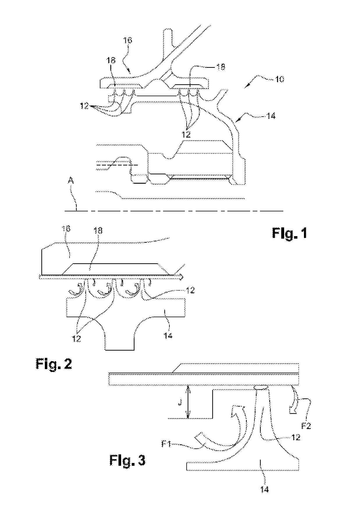
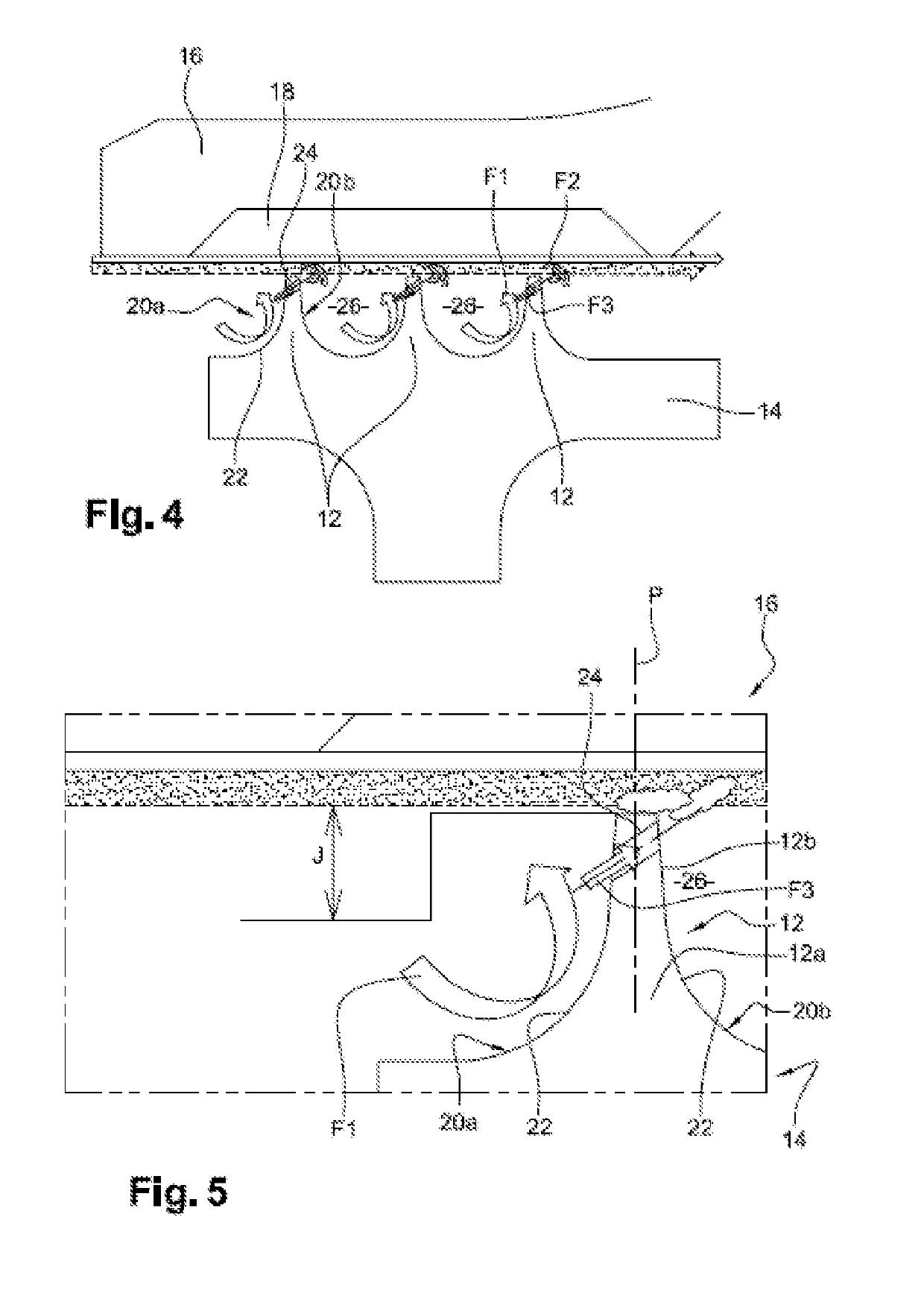
[0032]FIGS. 4 and 5 show the invention.

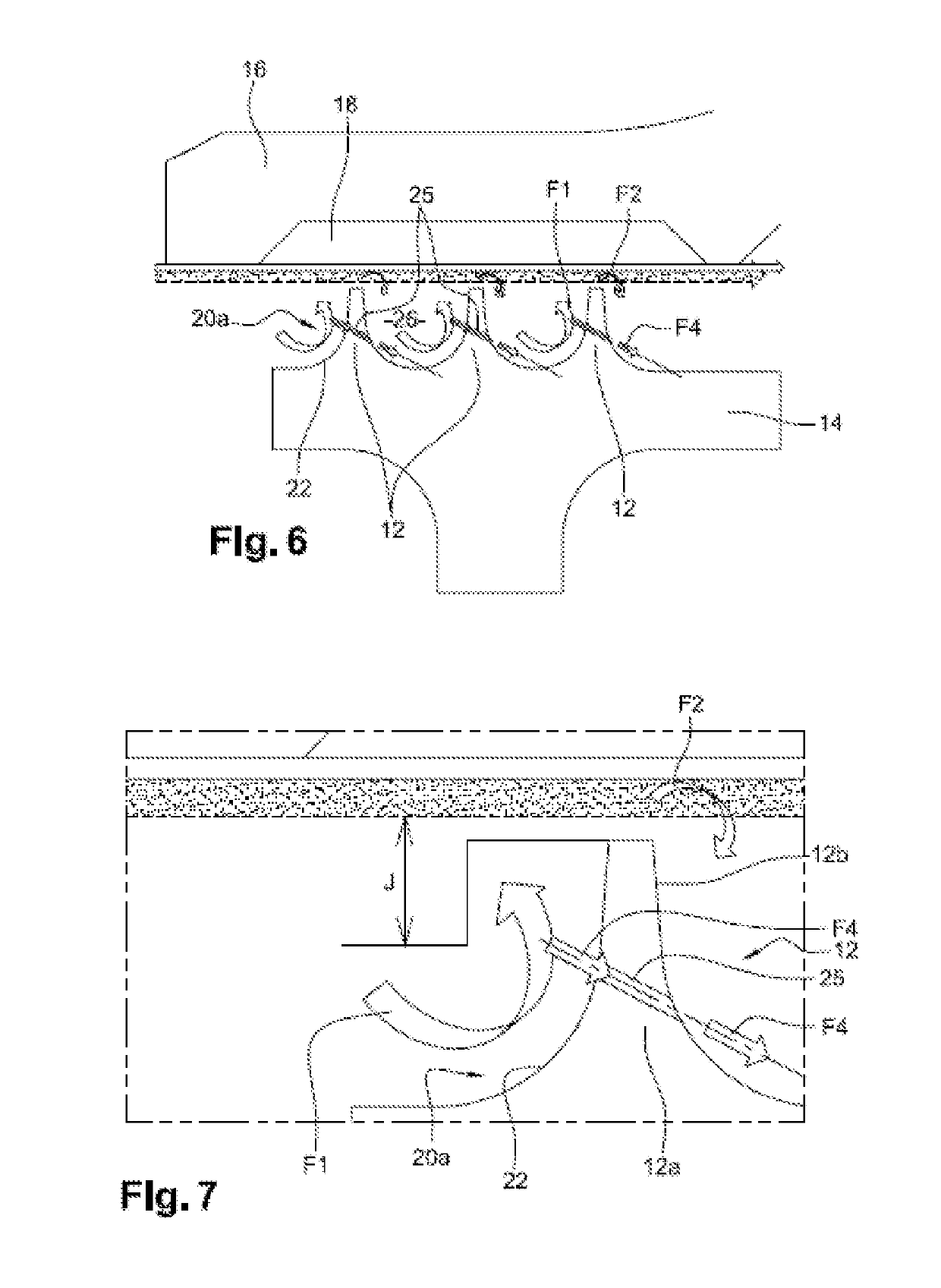
[0033]As in prior art, each lip 12 comprises an annular body 12a and a free annular top 12b, generally pointed, in other words, of which the width or axial dimension is less than that of the body 12a.

[0034]In the example shown, the lip 12 has a symmetry with respect to a median plane P substantially perpendicular to the axis of rotation of the rotor element 14.

[0035]Each lip 12 comprises an upstream annular face 20a and a downstream annular face 20b, the flow of gas flowing from upstream to downstream through the seal and more generally in the turbine engine, and from left to right in the drawings.

[0036]The lips 12 are separated from one another by annular spaces 26. The spaces 26 have a section with a general U-shape in the example shown.

[0037]The body 12a of each lip 12 comprises, in observation of the side of the upstream face 20a, an annular cavity 22 with a section with a concave rounded shape. Due to the symmetry of the body, the latter ...


PUM


Abstract

Labyrinth seal for a turbine engine, in particular of an aircraft, including a rotor element rotating about an axis of rotation (A), and a stator element extending around the rotor element (14), the rotor element including a series of annular lip(s) extending radially outwards and surrounded by at least one abradable element carried by the stator element, each lip comprising an inner peripheral body portion, an outer peripheral body portion, an upstream annular face of impact of an air flow during operation and a downstream annular face, wherein at least one lip includes, on the inner peripheral body portion thereof and/or the outer peripheral body portion thereof, through-orifices for the passage of air extending between the upstream and downstream annular faces.

Description

TECHNICAL FIELD[0001]The present invention relates to a labyrinth seal for a turbine engine, in particular of an aircraft.STATE OF THE ART[0002]The state of the art comprises especially document DE-T5-11 2015 000 575.[0003]It is known to equip a turbine engine with labyrinth seals which are dynamic seals whose sealing is provided by rotating lips. Such as is shown in FIG. 1, the lips 12 are carried by a rotor element 14 of the turbine engine 10, which rotates inside a stator element 16 and are surrounded by abradable elements 18 such as blocks or a coating of abradable material carried by this stator element 16.[0004]The abradable elements 18 have the purpose of protecting the lips 12 from risks of wear by contact with the element 16 that surrounds them. The contacts with the abradable elements 18 can be avoided or on the contrary sought for example in order to optimise the radial clearances J around the lips. The types of abradable elements 18 and lips 12 can be adapted in conseque...

Claims


Application Information

Patent Timeline
Patent Type & Authority Applications(United States)
IPC IPC(8): F01D11/00F01D11/02
CPCF01D11/001F01D11/02F05D2240/55F01D5/225F01D11/04F01D11/122F05D2260/607F05D2260/606Y02T50/60
Inventor JAROSSAY, CLEMENTVERRON, GUILHEM CAMILLE FRANCOISJUDET, MAURICE GUYLAROCHE, CLEMENT RAPHAELGILIBERTI, GUILLAUME MICHEL MAURICE
Owner SN DETUDE & DE CONSTR DE MOTEURS DAVIATION S N E C M A
Why Eureka
Try Eureka