
Optical Powder Spreadability Sensor and Methods for Powder-Based Additive Manufacturing

a spreadability sensor and optical sensor technology, applied in the field of additive manufacturing, can solve the problems of less than satisfactory results for another type of build procedure, insufficient to fully describe the spread behaviour, and may not be visible on the upper surface of the build, so as to optimize the smoothness of the optical sensor output, and improve the quality of the additive manufacturing process

Active Publication Date: 2019-04-11
EOS OF NORTH AMERICA INC
View PDF0 Cites 4 Cited by
  • Summary
  • Abstract
  • Description
  • Claims
  • Application Information

AI Technical Summary

Benefits of technology

The invention provides a method for improving the quality of additive manufacturing processes by quantifying the behavior of powder materials during build procedures. This helps to ensure consistent quality and avoid defects in the build, even if there are unpredictable behavior of the powder material. The method includes collecting information about the build procedure using the actual conditions and the specific type of powder material, and adjusting the operating parameters of the additive manufacturing apparatus accordingly to obtain a smooth powder pile surface. This improves powder distribution and quality of the build, without adding significant effort to the process.

Problems solved by technology

While these additional factors can usually be measured or otherwise determined, the Inventors have seen that these are insufficient to fully describe the spreading behaviour or “spread” of a powder.
As explained above, a material such as a powder that is used in an additive manufacturing process can be well-defined by various known and measurable properties such as particle size, packing density, flowability, etc., but even the knowledge of all these properties cannot prevent defects developing in a build, and a powder that gives very favorable results for one type of build procedure may give less than satisfactory results for another type of build procedure, even under essentially identical operating conditions.
Furthermore, the upper surface(s) of the build may not be essentially flat as intended, but may exhibit erratic projections that arise from residual stresses that develop during the melting and subsequent cooling of the powder material.
These irregularities or projections—even if they are very small—will also interact in unpredictable ways with the powder particles in the powder pile, resulting in erratic or random accumulations in the powder pile, and detracting from an optimal spreading behavior of the powder.

Method used


Image

  • Optical Powder Spreadability Sensor and Methods for Powder-Based Additive Manufacturing
  • Optical Powder Spreadability Sensor and Methods for Powder-Based Additive Manufacturing
  • Optical Powder Spreadability Sensor and Methods for Powder-Based Additive Manufacturing

Examples


Embodiment Construction

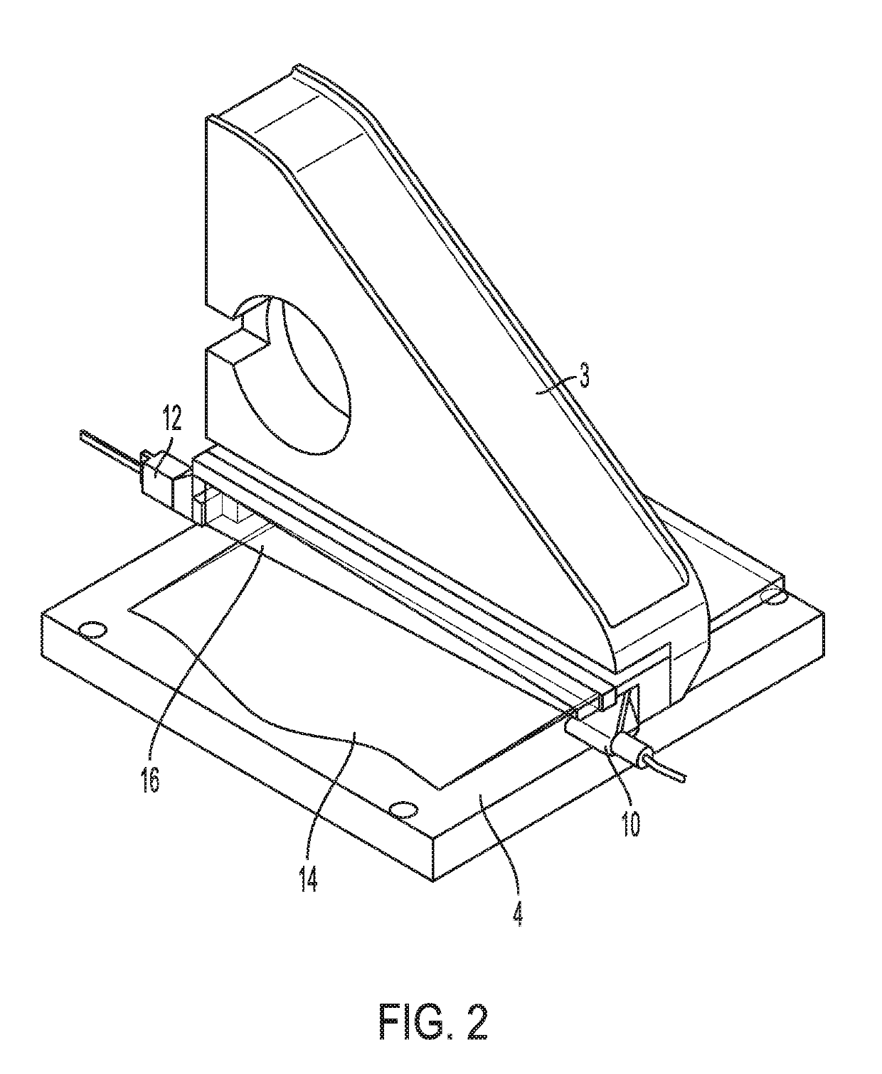
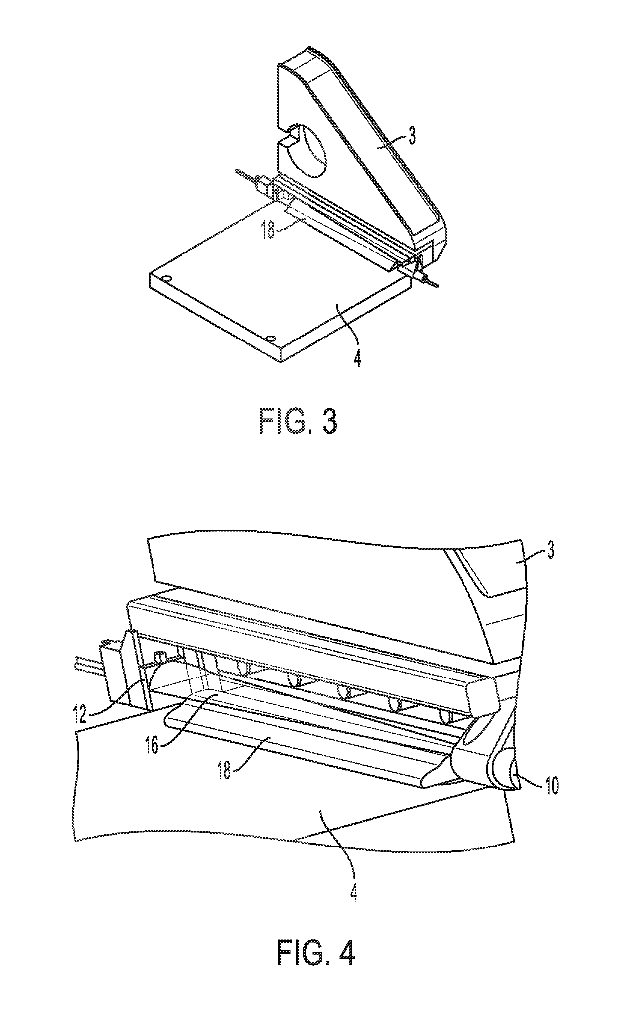
[0045]As noted, the present disclosure has found particular application in the production of objects, or workpieces, in an additive manufacture process which utilizes a radiant beam of energy, such as a laser, to solidify a fluent material, such as a powder, in a layer-wise build-up of the object. In a typical process of this type, a layer of powder is spread and smoothed over the top plane or surface of a build area in which the object is being generated. Each layer corresponds with a two-dimensional “slice” of the object, which is then solidified (e.g., fused, melted, sintered) from the powder. The object is built up by moving the solidified layer(s) incrementally downwardly in the build chamber, and a fresh layer of powder then being spread by a recoater (sometimes also referred to as a doctor blade, applicator, slide, refreshing device, roller and other names), which takes a charge or load of material deposited in front of the recoater and then moves that material across the bui...


PUM

PropertyMeasurementUnit
Widthaaaaaaaaaa
Surface smoothnessaaaaaaaaaa
Energyaaaaaaaaaa

Abstract

Disclosed is an apparatus for and method of determining spreading behavior of a powder material during an additive manufacturing process. The method deposits a powder mound, moves a spreader to distribute a layer of powder over a build supported on a build area, operates an energy source to cast intercept the powder mound in the path of the source and onto an optical sensor during displacement of the powder mound, and analyzes an output of the optical sensor to identify features relating to the spreading behavior of the powder.

Description

TECHNICAL FIELD OF THE INVENTION[0001]The present invention relates to the field of additive manufacturing, wherein successive layers of an object or workpiece are built up from a powder or other fluent medium according to previously determined successive so-called two-dimensional “slices” of the object or workpiece, and more particularly to a system and method for determining the spreadability of a powder layer being applied. The invention further describes a method of determining a spreading behavior of a powder material during an additive manufacturing process; a method of performing an additive manufacturing process; and an additive manufacturing apparatus.BACKGROUND OF THE INVENTION[0002]Additive prototyping or additive manufacturing (AM) techniques using a laser or other energy beam to melt, fuse, cure, sinter or otherwise solidify material to build an object or workpiece (hereafter simply referred to as an object) in a layer-wise manner are well known. In one standard approac...

Claims


Application Information

Patent Timeline
IPC IPC(8): B29C64/393B33Y10/00B33Y30/00B33Y50/02B28B1/00B28B17/00B22F3/105B29C64/153B29C64/214
CPCB29C64/393B33Y10/00B33Y30/00B33Y50/02B28B1/001B28B17/0081B22F3/1055B29C64/153B29C64/214B22F2003/1057Y02P10/25B22F10/31B22F10/28B22F12/67B22F12/90
Inventor SAHARAN, ANKITLASALLE, III, ERLING RICHARD
Owner EOS OF NORTH AMERICA INC
Learn More