
Semiconductor device and method of manufacturing semiconductor device

Active Publication Date: 2019-03-28
FUJI ELECTRIC CO LTD +1
View PDF5 Cites 12 Cited by
  • Summary
  • Abstract
  • Description
  • Claims
  • Application Information

AI Technical Summary

Benefits of technology

The semiconductor device and manufacturing method described in this patent make it possible to easily achieve the desired characteristics of a semiconductor device. This is particularly useful when performing lifetime control, which can affect the stability and efficiency of the device.

Problems solved by technology

When a sputtering technique is used to embed the front electrode in the contact hole having a small width, voids occur in the front electrode.

Method used


Image

  • Semiconductor device and method of manufacturing semiconductor device
  • Semiconductor device and method of manufacturing semiconductor device
  • Semiconductor device and method of manufacturing semiconductor device

Examples


Embodiment Construction

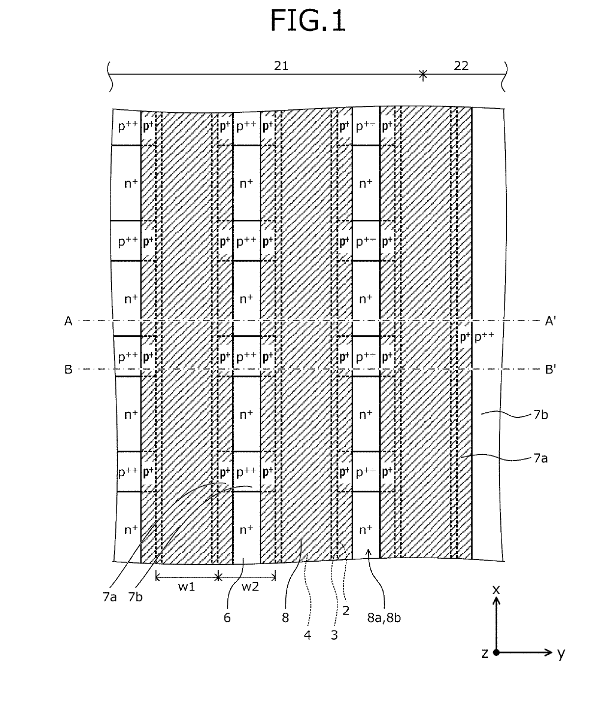
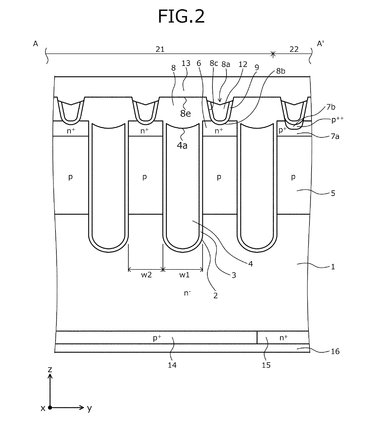
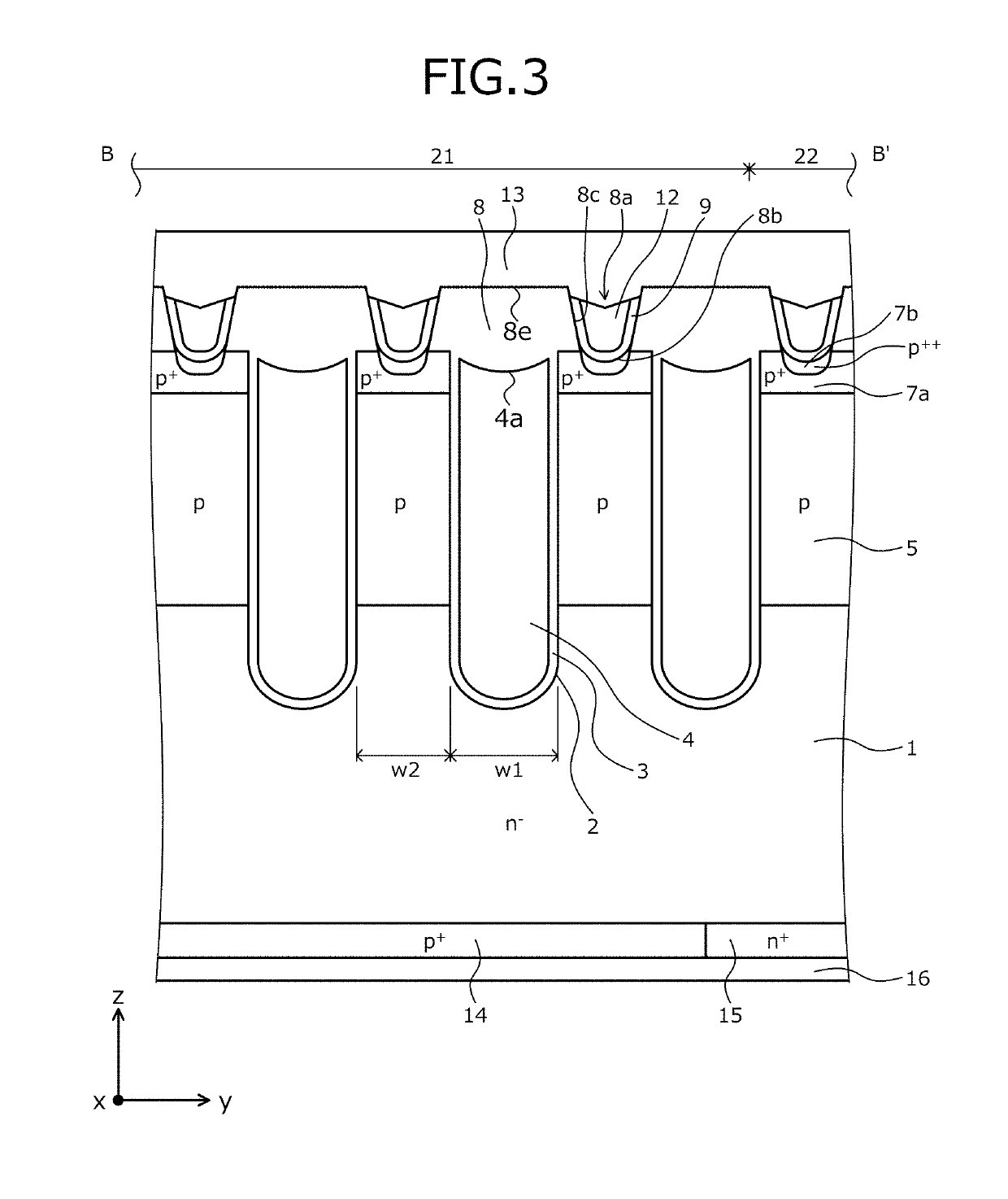
[0076]First, problems associated with the related arts will be described. As described above, in the first conventional structure depicted in FIG. 24, the entire surface of the interlayer insulating film 210 is covered by the barrier metal 211 and therefore, the recovery effect of the gate threshold voltage by hydrogen annealing is not obtained. This problem is solved by a configuration in which the barrier metal is not disposed in a part where a semiconductor part and the front electrode are not in contact like that in Japanese Laid-Open Patent Publication No. H06-310729. In this case, the recovery effect of the gate threshold voltage by hydrogen annealing may be obtained to an extent equal to that of a conventional structure (a structure in which no plug electrode is used: hereinafter, the second conventional structure) in which a front electrode made of aluminum is embedded in a contact hole.

[0077]Nonetheless, in Japanese Laid-Open Patent Publication No. H06-310729, a problem ari...


PUM


Abstract

A plug electrode is subject to etch back to remain in a contact hole and expose a barrier metal on a top surface of an interlayer insulating film. The barrier metal is subject to etch back, exposing the top surface of the interlayer insulating film. Remaining element structures are formed. After lifetime is controlled by irradiation of helium or an electron beam, hydrogen annealing is performed. During the hydrogen annealing, the barrier metal is not present on the interlayer insulating film covering a gate electrode, enabling hydrogen atoms to reach a mesa part, whereby lattice defects generated in the mesa part by the irradiation of helium or an electron beam are recovered, recovering the gate threshold voltage. Thus, predetermined characteristics of a semiconductor device having a structure where a plug electrode is provided in a contact hole, via barrier metal are easily and stably obtained when lifetime control is performed.

Description

CROSS REFERENCE TO RELATED APPLICATIONS[0001]This is a continuation application of International Application PCT / JP2017 / 033604 filed on Sep. 15, 2017 which claims priority from a Japanese Patent Application No. 2016-183126 filed on Sep. 20, 2016, the contents of which are incorporated herein by reference.BACKGROUND1. Field[0002]Embodiments of the invention relate to a semiconductor device and a method of manufacturing a semiconductor device.2. Description of Related Art[0003]Conventionally, in a semiconductor device having a trench gate structure in which an insulated gate constituted by a metal oxide film semiconductor (MOS) is embedded in a trench formed in a semiconductor substrate, trench pitch (interval at which trenches are disposed) is reduced to improve characteristics. Reduction of the trench pitch, reduces a width (mesa part) between adjacent trenches, whereby a width of a contact hole forming a contact (electrical contact part) of a front electrode and a semiconductor par...

Claims


Application Information

Patent Timeline
IPC IPC(8): H01L29/739H01L29/08H01L29/10H01L29/40H01L29/423H01L21/768H01L29/66
CPCH01L29/7397H01L29/0804H01L29/0821H01L29/1004H01L29/401H01L29/42368H01L29/42376H01L21/76816H01L29/66348H01L29/8613H01L29/417H01L29/456H01L29/7396H01L29/0696H01L29/0834
Inventor MIYATA, HIROSHINOGUCHI, SEIJIYOSHIDA, SOUICHITANABE, HIROMITSUKOUNO, KENJIOKURA, YASUSHI
Owner FUJI ELECTRIC CO LTD
Learn More