
Methods for sensitizing photoresist using flood exposures

a technology of flood exposure and photoresist, which is applied in the field of sensitizing photoresist using flood exposure, can solve the problems of increasing the lwr of the resist pattern, the inability to achieve the effect of reducing the euv sensitivity, and the inability to achieve the effect of reducing the lwr and resolution, and improving the sensitivity of the resist pattern

Active Publication Date: 2019-03-28
TOKYO ELECTRON LTD
View PDF0 Cites 6 Cited by
  • Summary
  • Abstract
  • Description
  • Claims
  • Application Information

AI Technical Summary

Benefits of technology

The patent describes a method for creating patterns in a target layer on a substrate using a light-sensitive layer. The method involves subjecting the light-sensitive layer to at least two exposures of radiative energy. The first exposure uses energy at a specific wavelength and a lower dose, while the second exposure uses energy at a different wavelength and a higher dose. The light-sensitive layer is then developed to create a mask pattern, which is used to etch the substrate and form the final pattern. The resulting pattern has better resolution and smoothness compared to a pattern formed using a single exposure. This method also reduces the sensitivity to extreme ultraviolet light and allows for greater patterning accuracy.

Problems solved by technology

Conventional techniques that seek to improve one of the three parameters often improve at the unacceptable expense of one or both of the other parameters.
However, EUV resist sensitivity (EUV dose) is one of the challenges for EUV lithography.
Standard means of increasing the resist sensitivity (such as by increasing the PAG concentration) have not proven beneficial in EUV systems because they reduce the number of photons required to achieve a certain line width and so increase shot-noise related LWR in the resist patterns.
Another challenge with EUV processing is getting the EUV scanner's source power high enough to account for this lower photon creation for equivalent dose to 193 nm exposure.
Raising the EUV exposure dose increases the number of photons, lowers throughput and increases operating cost.
Many researchers have tried to escape the RLS triangle and throughput challenges, but as of yet none have fully succeeded.

Method used


Image

  • Methods for sensitizing photoresist using flood exposures
  • Methods for sensitizing photoresist using flood exposures

Examples


Embodiment Construction

[0011]A method for patterning a substrate is disclosed in various embodiments. However, one skilled in the relevant art will recognize that the various embodiments may be practiced without one or more of the specific details, or with other replacement and / or additional methods, materials, or components. In other instances, well-known structures, materials, or operations are not shown or described in detail to avoid obscuring aspects of various embodiments of the invention.

[0012]Similarly, for purposes of explanation, specific numbers, materials, and configurations are set forth in order to provide a thorough understanding of the invention. Nevertheless, the invention may be practiced without specific details.

[0013]Reference throughout this specification to “one embodiment” or “an embodiment” or variation thereof means that a particular feature, structure, material, or characteristic described in connection with the embodiment is included in at least one embodiment of the invention b...


PUM

PropertyMeasurementUnit
roughnessaaaaaaaaaa
roughnessaaaaaaaaaa
wavelengthaaaaaaaaaa

Abstract

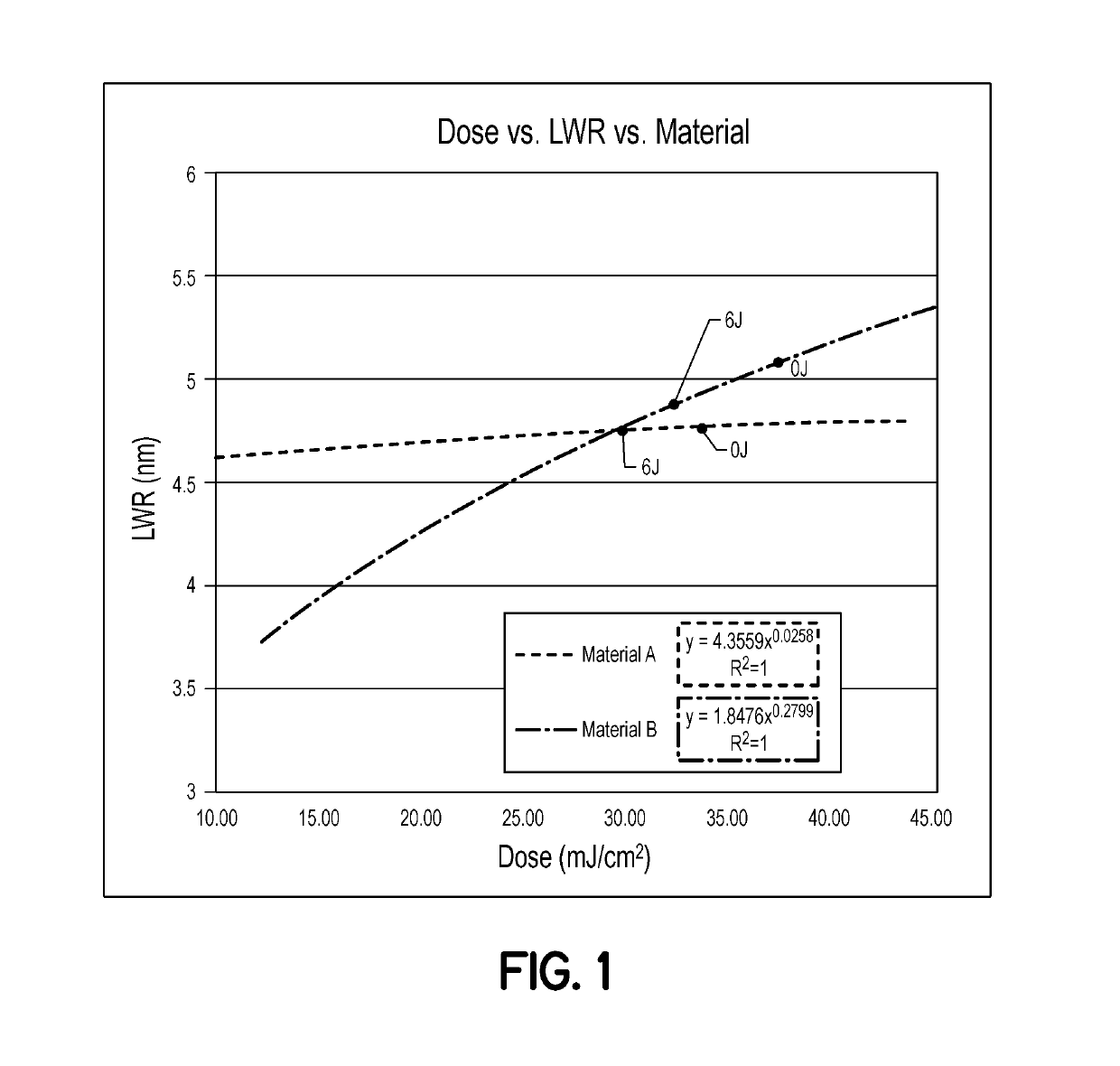
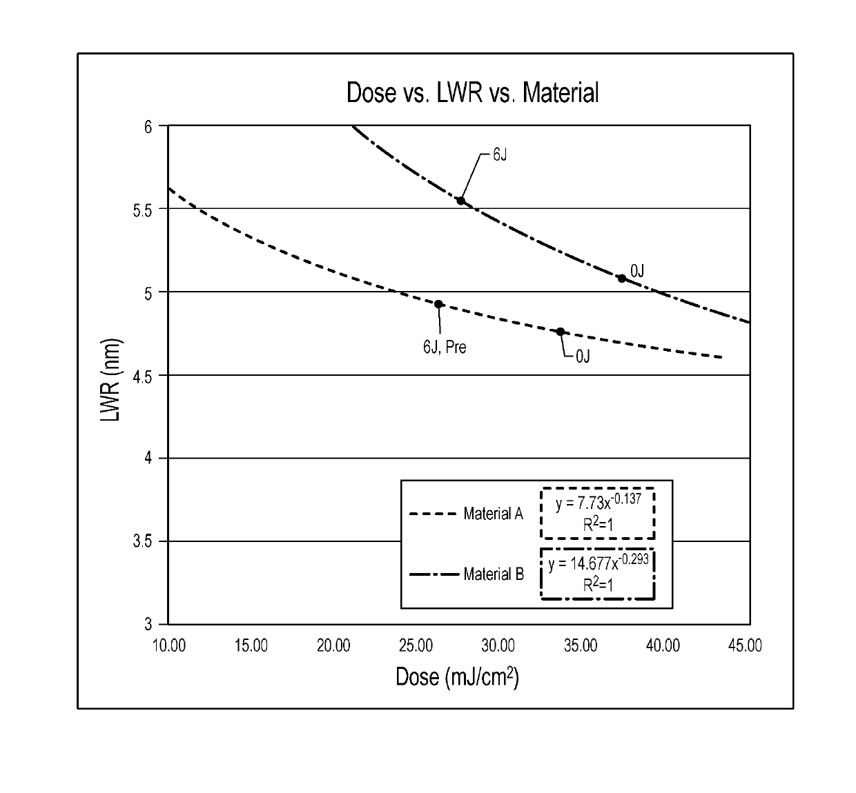
A patterning method is provided in which a light-sensitive layer is formed, and a target resolution is defined for a pattern to be formed in a target layer. Based on a reference dose and reference LWR that results from a single patterning exposure at an EUV wavelength, the target resolution and reference dose, the light-sensitive layer is subjected to at least two radiation exposures including an EUV patterning exposure at a dose selected to be less than the reference dose and within 15 mJ / cm2-200 mJ / cm2, and a flood exposure at a wavelength of 200 nm-420 nm and a dose of 0.5 J / cm2-20 J / cm2. The light-sensitive layer is then developed to form a mask pattern, which is used to etch the pattern into the target layer with the target resolution and a LWR less than or approximately equal to the reference LWR and ≤5 nm.

Description

FIELD OF INVENTION[0001]The invention relates to methods for patterning a target layer on a substrate, and more particularly to a method for reducing resist sensitivity while maintaining or improving line width roughness and resolution.BACKGROUND OF THE INVENTION[0002]In material processing methodologies, pattern etching comprises the application of a layer of light-sensitive (or radiation-sensitive) material, such as photoresist (or “resist” for short), to an upper surface of a substrate, the formation of a pattern in the resist layer using photolithography, and the transfer of the pattern formed in the resist layer to an underlying target layer (thin film) on the substrate using an etching process. The patterning of the resist generally involves exposure of the resist to a pattern of electromagnetic (EM) radiation using, for example, a photolithography system, followed by the removal of the irradiated regions of the resist (as in the case of positive tone resist), or non-irradiate...

Claims


Application Information

Patent Timeline
Patent Type & Authority Applications(United States)
IPC IPC(8): G03F7/20G03F7/40
CPCG03F7/2022G03F7/70033G03F7/40G03F7/0045G03F7/091
Inventor CARCASI, MICHAEL A.SOMERVELL, MARK H.NAGAHARA, SEIJI
Owner TOKYO ELECTRON LTD
Learn More