Moving-body lighting device and moving body

a technology for moving bodies and lighting devices, applied in the direction of lighting and heating apparatus, vehicle components, light sources, etc., can solve the problem of difficulty in ensuring sufficient design freedom, and achieve the effect of sufficient design freedom

Inactive Publication Date: 2019-03-28
PANASONIC INTELLECTUAL PROPERTY MANAGEMENT CO LTD
View PDF0 Cites 3 Cited by
  • Summary
  • Abstract
  • Description
  • Claims
  • Application Information

AI Technical Summary

Benefits of technology

[0008]With the present disclosure, it is possible to ensure sufficient design freedom.

Problems solved by technology

In such cases, since the first and second light-emitting devices are disposed proximate a corner of the region of the common heat sink corresponding to the first heat sink, it is difficult to ensure sufficient design freedom.

Method used


Image

  • Moving-body lighting device and moving body
  • Moving-body lighting device and moving body
  • Moving-body lighting device and moving body

Examples


embodiment 1

(Configuration)

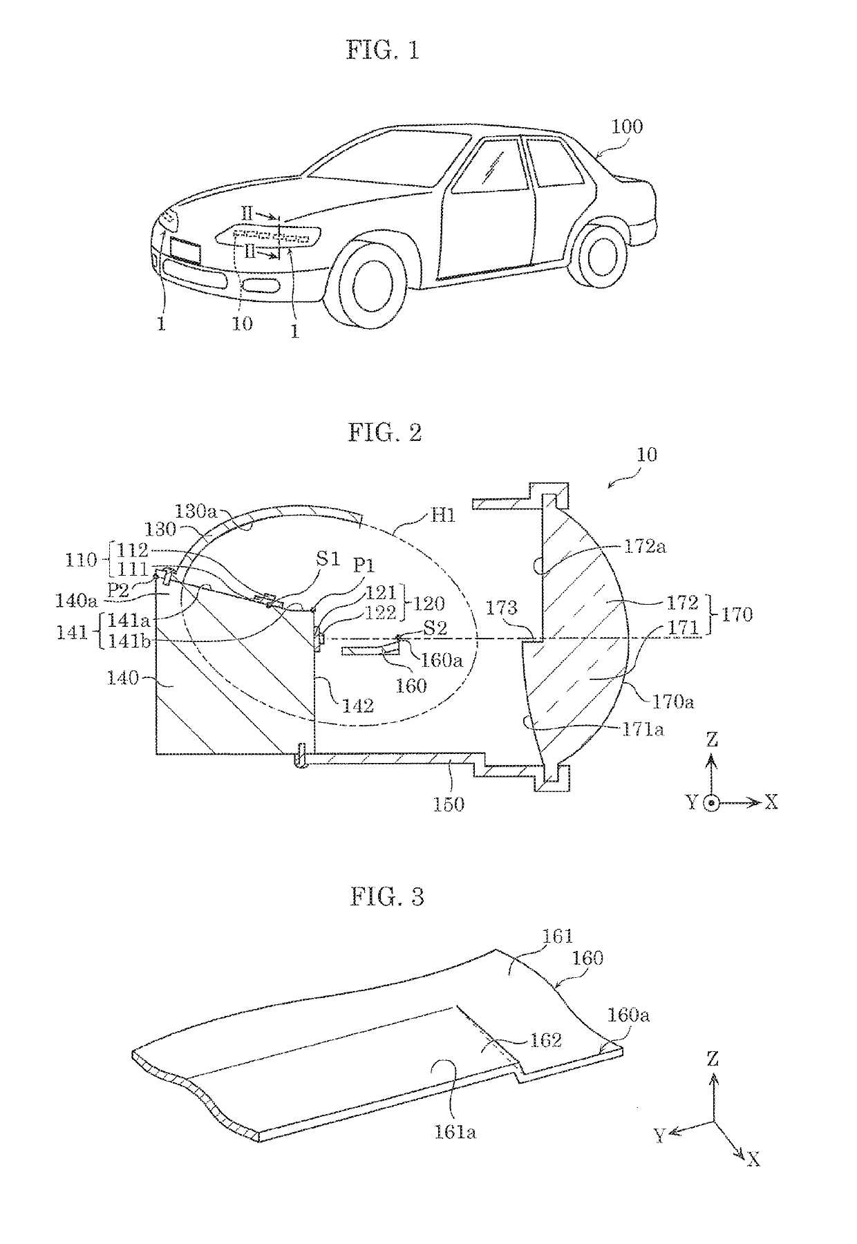
[0022]FIG. 1 schematically illustrates vehicle 100 according to Embodiment 1.

[0023]X, Y, and Z directions are shown in FIG. 2. The direction in which moving-body lighting device 10 emits light corresponds to the X axis positive direction, the direction pointing upward out of the drawing corresponds to the Y axis positive direction, and the direction in which first light source 110 emits light corresponds to the Z axis positive direction. The directions shown in FIG. 2 correspond to the directions shown in FIG. 3. This also applies to the drawings subsequent to FIG. 3, excluding the drawings in which the X, Y, and Z directions are not indicated.

[0024]As illustrated in FIG. 1, moving-body lighting device 10 is used in vehicle 100, and, more specifically, is included in headlight 1 of vehicle 100. Moving-body lighting device 10 is electrically connected to the electric system in vehicle 100. Vehicle 100 is one example of the moving body.

[0025]FIG. 2 is a cross-sectional ...

embodiment 2

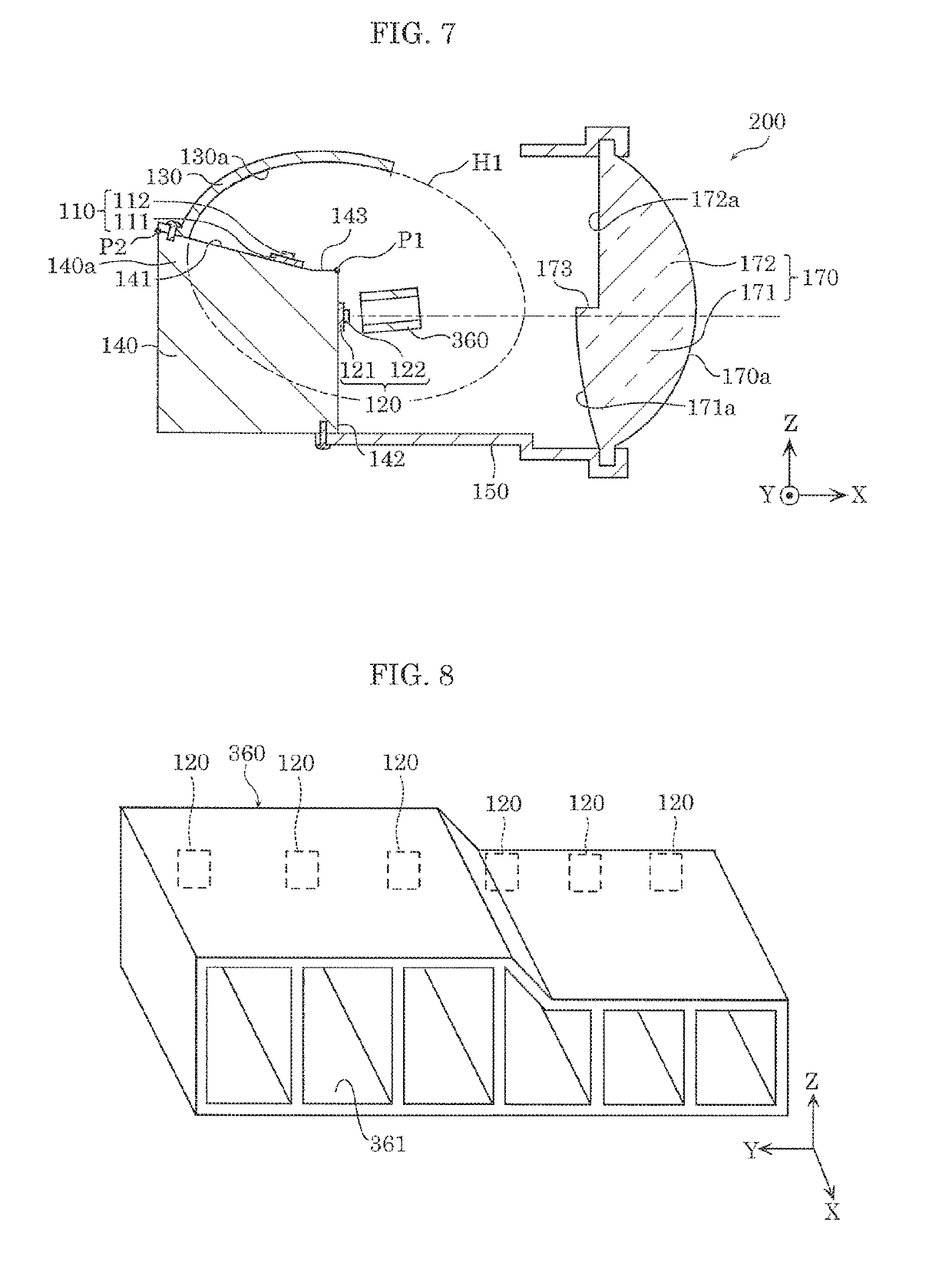
[0098]FIG. 7 is a cross-sectional view of moving-body lighting device 200 according to Embodiment 2. FIG. 8 is a perspective view of reflective tube 360 in moving-body lighting device 200 according to Embodiment 2.

[0099]This embodiment differs from Embodiment 1 in that moving-body lighting device 200 includes reflective tube 360 disposed on the X axis positive direction side of a plurality of second light sources 120. Unless otherwise stated, moving-body lighting device 200 according to this embodiment has the same configuration as described Embodiment 1. Accordingly, like elements share like reference signs in the drawings, and repeated detailed description of those elements is omitted.

[0100]As illustrated in FIG. 7 and FIG. 8, a plurality of second light source 120 are aligned parallel to the Y axis. In this embodiment, second light sources 120 are aligned in a single row, but second light sources 120 may be aligned in two or more rows. In other words, second light source 120 may ...


PUM


Abstract

A moving-body lighting device includes: a first light source; a second light source that is disposed forward of the first light source and emits light forward; a reflector in a shape of a segment of a spheroid, and that reflects the light emitted by the first light source; a projection lens that receives the light emitted by the first light source and reflected by the reflector; and a shade disposed between the second light source and the projection lens, proximate a second focal point. The projection lens includes a first lens region that receives the light emitted by the first light source and reflected by the reflector, and a second lens region that receives the light emitted by the second light source. The major axis of the spheroid is oblique to a horizontal axis.

Description

CROSS REFERENCE TO RELATED APPLICATION[0001]This application claims the benefit of priority of Japanese Patent Application Number 2017-187031 filed on Sep. 27, 2017, the entire content of which is hereby incorporated by reference.BACKGROUND1. Technical Field[0002]The present disclosure relates to a moving-body lighting device and a moving body.2. Description of the Related Art[0003]A lighting device for use in a vehicle that emits light forward and includes a first light-emitting device for generating a high beam that is mounted toward an edge of a substrate, a second light-emitting device for generating a low beam, and a lens body disposed forward of the first and second light-emitting devices is known (for example, see Japanese Unexamined Patent Application Publication No. 2015-216019).SUMMARY[0004]In the vehicle lighting device disclosed in Japanese Unexamined Patent Application Publication No. 2015-216019, when a single, common heat sink is used for the first heat sink attached ...

Claims


Application Information

Patent Timeline
Patent Type & Authority Applications(United States)
IPC IPC(8): F21V29/74F21S41/275F21S41/24F21S41/32F21S41/692
CPCF21V29/74F21S41/275F21S41/24F21S41/321F21S41/692F21Y2115/10F21S41/143F21S41/147F21S41/255F21S41/43F21S41/663
Inventor NISHI, TETSUYA
Owner PANASONIC INTELLECTUAL PROPERTY MANAGEMENT CO LTD
Why Eureka
Try Eureka