Device for generating microspheres from a fluid, method of injecting at least one first fluid into a second fluid, and an injection plate

a technology of microspheres and fluids, applied in water supply installations, lighting and heating apparatuses, combustion types, etc., can solve problems such as droplet formation, achieve the effects of preventing contamination, maximizing speed, and increasing the period of reliable operation

Active Publication Date: 2012-01-24
NANOMI BV
View PDF10 Cites 25 Cited by
  • Summary
  • Abstract
  • Description
  • Claims
  • Application Information

AI Technical Summary

Benefits of technology

[0013]In a preferred embodiment, the device according to the invention has the feature that the injection channel has a number of laterally bounded side extensions which extend from the outflow opening to at least the break-up point, and that neighbouring extensions are immediately adjacent of each other and herein mutually enclose a pointed wall part of the injection channel. The pointed, sharp wall parts between successive extensions reduce the contact surface for the forming droplet, and this enhances and accelerates a final break-off of the droplet. In this manner it is possible to realize an at least practically mono-dispersed break-up, wherein a cross-flow of any significance does not have to be applied, or hardly so, on the outlet side, and a sufficiently powerful droplet delivery is nevertheless achieved. Such pointed wall parts also prevent penetration of the first fluid into the secondary channel at the contact surface with the injection channel.
[0023]In a further particular embodiment, a device according to the invention has the feature that the injection channel extends substantially laterally in the injection plate, that the at least one secondary channel opens onto a free surface part of the injection plate with at least one perforation of a first dimension, and that the injection channel debouches on the outlet side of the injection plate into at least one perforation of a second, larger dimension. The injection channel is herein arranged lengthwise in the injection plate, wherein via one or more relatively small perforations in a wall of the injection channel at the position of the break-up point the first fluid in the injection channel can enter into direct contact with the auxiliary fluid provided at that position. The droplets appear from the outflow opening of the injection channel in the form of one or more larger perforations. In this embodiment a path length, and thereby a flow resistance to the auxiliary fluid to the break-up point, can be relatively small and additional freedom of design is obtained because the outflow opening does not have to lie in line with the injection channel. In addition, this embodiment provides the option of varying the injection channel along its length, which also provides extra design freedom.

Problems solved by technology

This mechanism moreover still results in droplet formation even without cross-flow on the outlet side of the injection plate.

Method used


Image

  • Device for generating microspheres from a fluid, method of injecting at least one first fluid into a second fluid, and an injection plate
  • Device for generating microspheres from a fluid, method of injecting at least one first fluid into a second fluid, and an injection plate
  • Device for generating microspheres from a fluid, method of injecting at least one first fluid into a second fluid, and an injection plate

Examples


Embodiment Construction

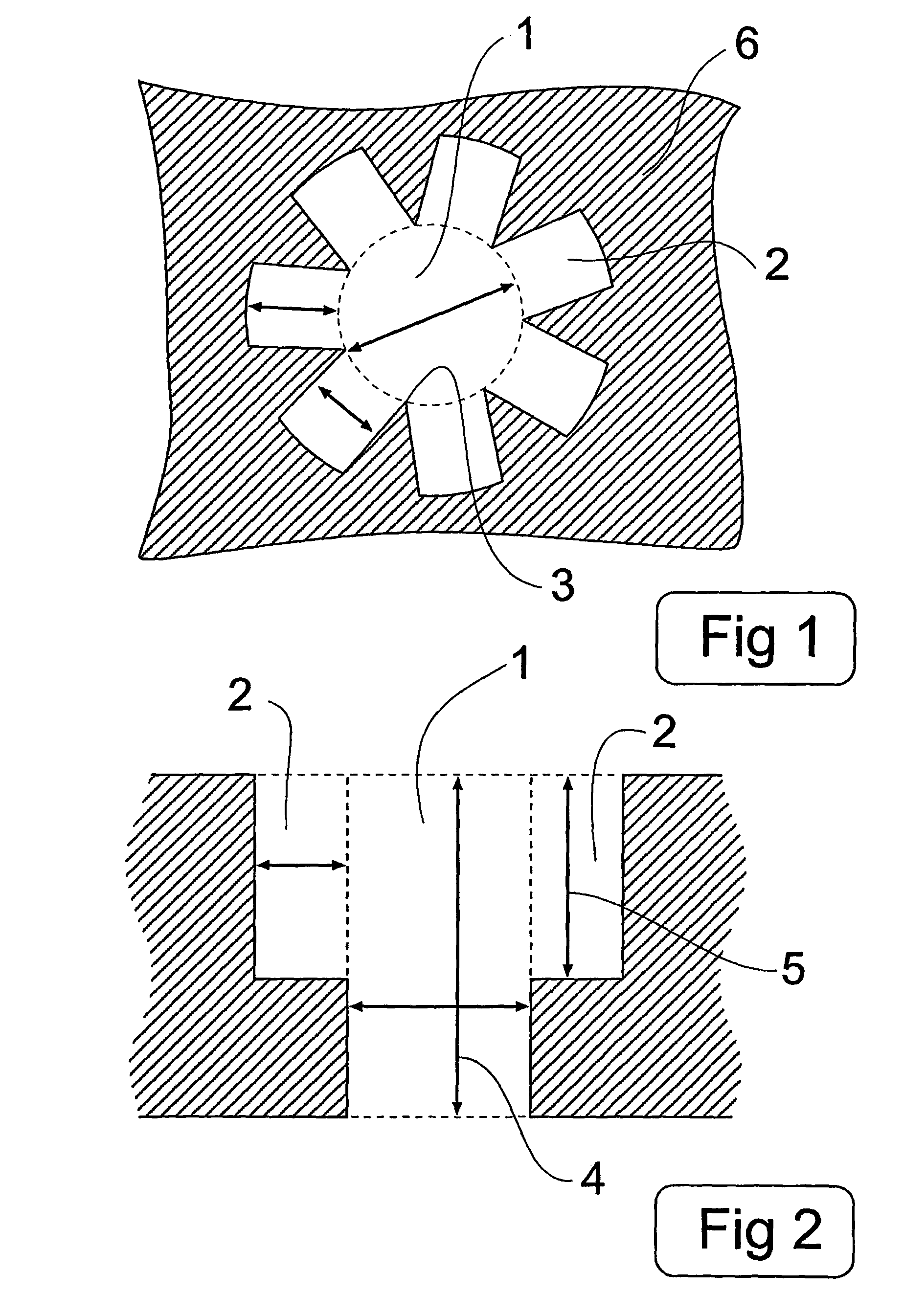
[0053]FIG. 1 shows a cross-section of an embodiment of the device according to the invention based on an injection plate 6 according to the invention having therein an injection channel 1 and secondary channels 2 in the form of side extensions with a practically quadrangular cross-section. In this embodiment the injection channel is round but, within the scope of the invention, a different form can be chosen herefor, as also for the extensions 2, for instance a rectangle, a polygon, an ellipse, a circle, a star shape or a sequence of forms. With a careful dimensioning of the effective diameter of injection channel 1 relative to an effective diameter of extensions 2, a sufficiently high inflow resistance can be given to these latter to a fluid carried through the injection channel so as to enclose the fluid at least almost completely in injection channel 1. Different side extensions can be mutually connected so as to thus reduce a flow resistance of the assembly of secondary channels...


PUM

PropertyMeasurementUnit
diameteraaaaaaaaaa
diameteraaaaaaaaaa
thicknessaaaaaaaaaa

Abstract

A device for generating microspheres from a fluid includes an injection plate with at least one defined injection channel having on an inlet side an inflow opening for receiving the fluid and on an outlet side an outflow opening for delivering microspheres formed from the fluid. The device includes feed elements for carrying fluid through the injection channel and is in open communication, on a side wall thereof, with at least one secondary channel at least at the position of a break-up point where at least during operation a flow of fluid in the injection channel breaks up into separate parts. The secondary channel includes in use an auxiliary fluid at least at the position of a break-up point.

Description

FIELD OF THE INVENTION[0001]The present invention relates to a device for generating microspheres from a fluid, comprising an injection plate which comprises at least one defined injection channel having on an inlet side an inflow opening for receiving the fluid and on an outlet side an outflow opening for delivering microspheres formed from the fluid, and provided with feed means for carrying the fluid through the injection channel. The invention also relates to a method for injecting at least one first fluid into a second fluid, and to an injection plate. The invention relates particularly here to the generating of microspheres from an injection channel with an effective diameter of between 0.1 and 50 micrometers, for the purpose of injecting small liquid microdroplets into a liquid in order to obtain an emulsion, or gas microbubbles into a liquid in order to obtain a foam. It is noted here that where for the sake of brevity droplets or microdroplets are mentioned hereinbelow, unl...

Claims


Application Information

Patent Timeline
Patent Type & Authority Patents(United States)
IPC IPC(8): A62C5/02B01F3/08B01F5/04B01F13/00
CPCB01F3/0807B01F5/0475B01F5/0476B01F5/0485B01F13/0059B01F2215/0427B01F2215/0431Y10T137/0357Y10T137/212B01F23/41B01F25/31421B01F25/3142B01F25/31425B01F33/30
Inventor WISSINK, JEROENVAN RIJN, CORNELIS JOHANNES MARIANIJDAM, WIETZEGOETING, CHRISTIAAN HALDIRHESKAMP, IWAN RUTGERVELDHUIS, GERRIT JAN
Owner NANOMI BV
Why Eureka
Try Eureka