
Lightweight rocker arm frame and curved crown part forming process thereof

a rocker arm and forming process technology, applied in the direction of valve arrangements, machines/engines, mechanical equipment, etc., can solve the problems of poor rigidity, affecting the normal operation of the engine, and the risk of fatigue fracture, so as to achieve a small rotational inertia and a simple forming process

Active Publication Date: 2019-03-28
HANGZHOU XZB TECH
View PDF1 Cites 0 Cited by
  • Summary
  • Abstract
  • Description
  • Claims
  • Application Information

AI Technical Summary

Benefits of technology

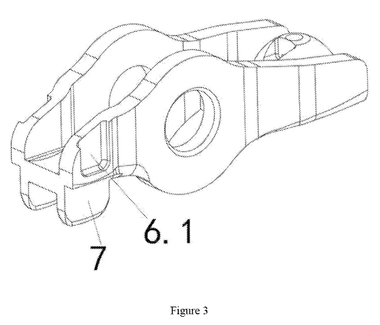
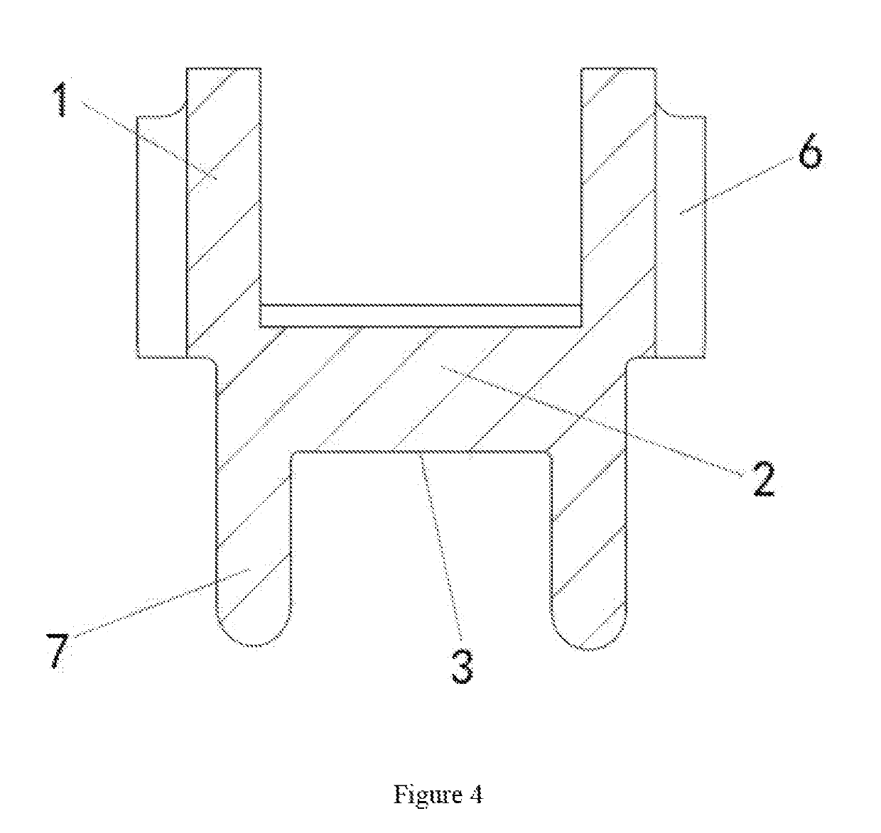
The invention is a novel lightweight rocker arm frame and a curved crown part forming process. The structure of the curved crown part does not need to go through U-shaped bending, extrusion, or folding. Instead, the sidewalls of the rocker arm frame are directly extruded to form the extruded sidewalls of the curved crown of the rocker arm frame. This strengthens the original structure while making it lightweight, which simplifies the forming process and saves costs.

Problems solved by technology

1. The local stretching and thinning phenomenon of the sidewall is serious, which influences the structural strength, resulting in the risk of fatigue fracture.
2. A gap exists between the two sidewalk which are not attached to each other, so the rigidity is poor and vibration noise can be generated during working, affecting normal operations of the engine.
3. More material is needed to fold the curved crown of the rocker arm frame, and thus the requirement for lightweight of the existing engine cannot be met.
4. The rocker arm frame forming process is complex and the cost is relatively high.

Method used


Image

  • Lightweight rocker arm frame and curved crown part forming process thereof
  • Lightweight rocker arm frame and curved crown part forming process thereof
  • Lightweight rocker arm frame and curved crown part forming process thereof

Examples


Embodiment Construction

[0036]The present invention is further described by the following embodiments and the accompanying drawings.

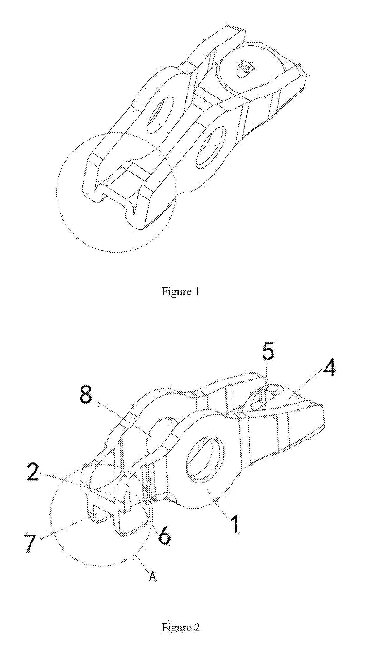
[0037]As shown in FIG. 1, the structure of a rocker arm frame in the prior art is provided. The curved crown part of the rocker arm frame is W-shaped. The forming process is that the plate material is firstly bent to form a U shape, which is then extruded and folded upwards to form a W shape. The defects of the forming process are that the side plate of the rocker arm frame becomes much thinner at the stretching position, so that the structural strength is influenced, resulting in the risk of fatigue fracture. Further, more material is used for folding and forming, the rotational inertia is large, failing to meet the requirement of light weight. Additionally, the depth of the W-shaped valve assembly bearing surface is small and has a gap. In the working state of the engine, particularly, when the valve assembly and the roller rocker arm are cold started, the valve rod has the ...


PUM


Abstract

This invention provides a novel lightweight rocker arm frame and a forming process of a curved crown part thereof, including two sidewalls and two bottom plates. The two sidewalls are connected through the bottom plates respectively located at two ends. A ball socket protruded upwards and an, oil hole are arranged at a bottom plate at one end, and a bottom surface of a bottom plate at the other end is a bearing surface. A pin shaft hole is formed in the middle of each sidewall without the bottom plates. According to the rocker arm frame disclosed by the invention, the strength of the structure can be ensured while light weight is realized. The production efficiency of the rocker arm frame is effectively improved, and the structure of the valve rod supporting position is improved.

Description

TECHNICAL FIELD[0001]The invention relates to the technical field of engine accessory manufacturing, particularly to a lightweight rocker arm frame and a curved crown part forming process thereof.BACKGROUND OF THE INVENTION[0002]With the increase in the driving, speeds of the automobiles and the increasing attention towards environmental protection, the innovation in the engine technology is developing in the direction of making engines having light weight, high efficiency, energy conservation and emission reduction. The gas distribution mechanism is an important part of an automobile engine. Since the rocker arm frame serves as a key part of the gas distribution mechanism, improvements in the structure of the rocker arm frame have important significance on the development of the engine.[0003]As shown in FIG. 1, the rocker arm frame structure in the prior art is formed by stamping a metal plate. One end of the rocker arm frame is a ball socket, and the other end of the rocker arm fr...

Claims


Application Information

Patent Timeline
Patent Type & Authority Applications(United States)
IPC IPC(8): F01L1/18
CPCF01L1/18F01L2103/01F01L1/181B21D53/84F01L1/185F01L2303/00F01L2305/00Y02T10/86F01L2303/01
Inventor XU, NAREN, HAIJUN
Owner HANGZHOU XZB TECH
Learn More