
Method and device for measuring the depth of the vapor capillary during a machining process with a high-energy beam

a technology of machining process and vapor capillary, which is applied in the direction of interferometers, manufacturing tools, instruments, etc., can solve the problems of welding through, undesirable variations in the penetration depth, and unsatisfactory solutions, and achieve the effect of reliable and accurate determination

Active Publication Date: 2019-03-28
PRECITEC OPTRONIK GMBH
View PDF0 Cites 6 Cited by
  • Summary
  • Abstract
  • Description
  • Claims
  • Application Information

AI Technical Summary

Benefits of technology

The invention provides a method and device to accurately determine the depth of a vapor capillary during a machining process with a high-energy beam despite interferences. This is achieved by selecting an earlier time and using a moving average or exponentially smoothed average to eliminate the effect of faster-changing interferences. The technical effect is to improve the accuracy of the vapor capillary depth measurement.

Problems solved by technology

A problem that was previously unsatisfactorily solved when welding or drilling with the aid of laser beams, was keeping the penetration depth of the laser beam at the desired setpoint as accurately as possible.
On the other hand, if the penetration depth is too deep, this may lead to welding through.
Undesirable variations in the penetration depth may occur for different reasons.
In addition, inhomogeneities in the workpieces or variations in the travel speed may cause the penetration depth to change locally and thus deviate from its setpoint.
The measurement of the depth of the vapor capillary presents a significant challenge because very difficult measuring conditions prevail within the vapor capillary.
Comparable problems also arise when machining workpieces with electron beams or other high-energy beams.
One problem with such measurements is that the coherence tomographs provide a lot of measurement data from which the desired information must be filtered out.
Significant problems arise in this case with respect to interferences, which partially cover the actually desired measurement signals.

Method used


Image

  • Method and device for measuring the depth of the vapor capillary during a machining process with a high-energy beam
  • Method and device for measuring the depth of the vapor capillary during a machining process with a high-energy beam
  • Method and device for measuring the depth of the vapor capillary during a machining process with a high-energy beam

Examples


first embodiment

[0109]To solve this problem, it is proposed according to the invention, that each interference spectrum Pint,tn(k), that was generated at time tn, the spectrum Pint,tn-1 (k), that was generated at the immediately preceding instant tn-1, are subtracted at least partially and preferably completely according to equation (3):

ΔPint,tn(k)=Pint,tn(k)−Pint,tn-1(k)  Eq.3

[0110]The Fourier transform is then supplied only for the thus calculated difference spectrum ΔPint,tn(k).

[0111]FIG. 10 illustrates this with reference to a graph in which a difference spectrum ΔPint,tn(k) is shown by way of example. It was assumed here that at the time tn-1, a disturbed interference spectrum was obtained, which represents a distance value of z=24 mm, and at time tn, a disturbed interference spectrum was obtained which represents a distance value z=20 mm. Since the interference spectrum 123 does not change, or changes only insignificantly, between two immediately successive times tn, tn-1, the influence of th...

second embodiment

[0121]In a second embodiment, another approach is taken to reduce the impact of interferences on the measurement. For this purpose, each interference spectrum Pint,tn(k), which was generated at time tn, divided by an average interference spectrum P(k), which is an average of a plurality of interference spectra, which were generated at earlier times tj, where j<m.

[0122]To explain this second approach, reference is first made to FIG. 12, which shows an undisturbed interference spectrum 132 generated by the coherence tomograph 40 after being divided by the above-mentioned white spectrum. This eliminates the equation Pein(k) in equation (1), which otherwise leads to undesired widening of the distance peaks in the Fourier transform of the measured interference spectrum. In addition, the signal was windowed in a manner known per se with a cos2 function 134 in order to reduce the smearing in Fourier space. Here, for the sake of simplicity, only the reflection at a single interface is consi...


PUM

PropertyMeasurementUnit
Timeaaaaaaaaaa
Interferenceaaaaaaaaaa
Depthaaaaaaaaaa

Abstract

A method for measuring the depth of the vapour cavity during an industrial machining process employs a high-energy beam. An optical measuring beam is directed towards the base of a vapour cavity. An optical coherence tomograph generates interference factors or other raw measurement data from reflections of the measurement beam. An evaluation device generates interference-suppressed measurement data, wherein raw measurement data that is generated at different times is processed together in the course of a mathematical operation. This operation can be a subtraction or a division. Slowly changing interference factors can thus be eliminated. An end value for the distance to the base of the vapour cavity is calculated from the interference-suppressed measurement data using a filter. As a result, the depth of the vapour cavity can be determined, in the knowledge of the distance at a part of the surface of the work piece that is not exposed to the high-energy beam.

Description

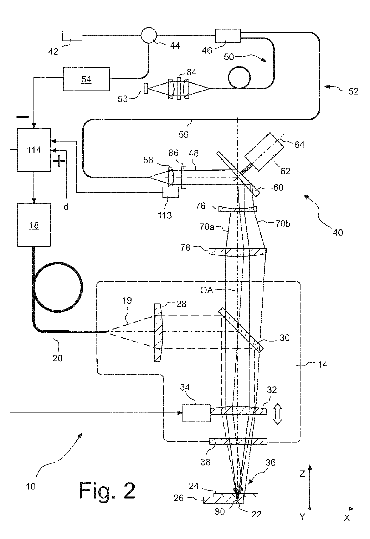
BACKGROUND OF THE INVENTION1. Scope of the Invention[0001]The invention relates to a method and a device for measuring the depth of the vapor capillary during a process in which workpieces are welded with a laser beam, an electron beam or another high-energy beam, provided with holes or processed in any other way. In particular, the invention relates to the mathematical evaluation of the measurement data generated by an optical coherence tomograph and superimposed by interferences.2. Description of the Prior Art[0002]Laser processing devices usually comprise a laser radiation source, which may be, for example, a fiber laser or a disk laser, and a machining head that focuses the laser beam generated by the laser beam source in a focal spot. The machining head may be attached to a movable robotic arm or other traveling device that allows positioning in all three spatial directions. Sometimes the machining head is fixed in space, and the workpieces are delivered by means of a handling ...

Claims


Application Information

Patent Timeline
IPC IPC(8): B23K26/03B23K26/04B23K26/08B23K26/21B23K26/06G01B11/22G01B9/02
CPCB23K26/032B23K26/048B23K26/0884B23K26/21B23K26/0665G01B11/22G01B9/02019G01B9/02044G01B9/02091B23K26/03G01B9/02083G01B2290/65B23K26/0643B23K26/0648
Inventor SCHONLEBER, MARTINDIETZ, CHRISTOPH
Owner PRECITEC OPTRONIK GMBH
Learn More