
System and method for determining a vital sign of a subject

a vital sign and system technology, applied in the field of patient monitoring systems and methods, can solve problems such as unresolved problems, alarm noise levels around 80 db, and caregivers' desensitization against alarms, and achieve the effect of reliably reducing the probability of false alarms and significantly reducing the probability

Active Publication Date: 2018-05-29
KONINKLJIJKE PHILIPS NV
View PDF34 Cites 2 Cited by
  • Summary
  • Abstract
  • Description
  • Claims
  • Application Information

AI Technical Summary

Benefits of technology

[0008]It is an object of the present invention to provide an improved system and method for determining a vital signs of a subject by which the false alarm probability is reliably and considerably reduced. It is another object of the present invention to provide a sensor for use in such a system and method.
[0020]The present invention therefore proposes the integration of a marker with the (medical) sensor. By use of the—often already available imaging unit (e.g. of a remote PPG system or a video actigraphy system)—image data of a certain imaging region, in which the sensor is located are obtained so that movements of the sensor can be reliably and accurately determined from the detected motion of the marker identified in the image data. Thus, a real-time analysis of the motion trajectories of the marker can be made from the image data that provides direct evidence on the sensor's motion and signal reliability. This evidence can then be used by the alarm unit to reduce the false alarm probability.
[0030]Preferably, said image analysis unit is configured to detect the location of said marker and one or more additional markers attached to one or more further sensors and / or to the subject's body from said image data. Further, said alarm unit is configured to generate and output an alarm signal if is detected that a sensor is not attached or attached incorrectly or to a wrong portion of the subject's body and / or is attached to a wrong subject. Thus, by use of several markers several sensors and subjects can be easily distinguished, and also certain situations of wrong use or malfunction of a sensor can be detected.
[0031]Still further, in an embodiment said alarm unit is configured to generate and output an alarm signal if the marker cannot be detected in said imaging region. This enables the detection of situations when a sensor is covered, e.g. by a blanket, or fell off from the patient, or even a situation when a patient is no longer in the imaging region at all, e.g. fell off from the bed.
[0034]In a preferred embodiment the sensor is a plethysmographic sensor comprising at least one light source for emitting light onto skin covered by said sensor, wherein said sensor is designed such that light from at least one light source is emitted in a direction away from the skin so that said light source functions as active marker. Thus, it is proposed to reuse one or more light sources (e.g. LEDs, for instance an invisible infrared LED), which are already integrated in the sensor, along with its existing wiring to facilitate the light beacon functionality.
[0035]Preferably, in an embodiment at least part of the sensor housing that carries the one or more light sources is made from a translucent material. This ensures that the sensor can be seen from many (preferably all) directions, i.e. the detection of the light source (as marker) is not (much) dependent on the actual position of the subject's hand. As an additional effect, the large surface of the sensor works as a light emitter and achieves a closer to 360 degrees emission pattern.

Problems solved by technology

It is well known that the frequent occurrence of false medical alarms in the hospital, e.g., alarms generated by patient monitoring devices in the intensive care unit (ICU), presents a serious and unresolved problem because it leads to a desensitization of the caregivers against alarms.
Furthermore, it is known that the high sensitivity of modern patient monitoring systems leads to alarm noise levels around 80 dB in today's average ICUs, which is comparable to the traffic noise on a main street.
However, up to 90% of the registered alarms are medically irrelevant.
The technical alarms, which make up about 22% of all alarms, are often due to bad sensor signals due to patient motion.

Method used


Image

  • System and method for determining a vital sign of a subject
  • System and method for determining a vital sign of a subject
  • System and method for determining a vital sign of a subject

Examples


first embodiment

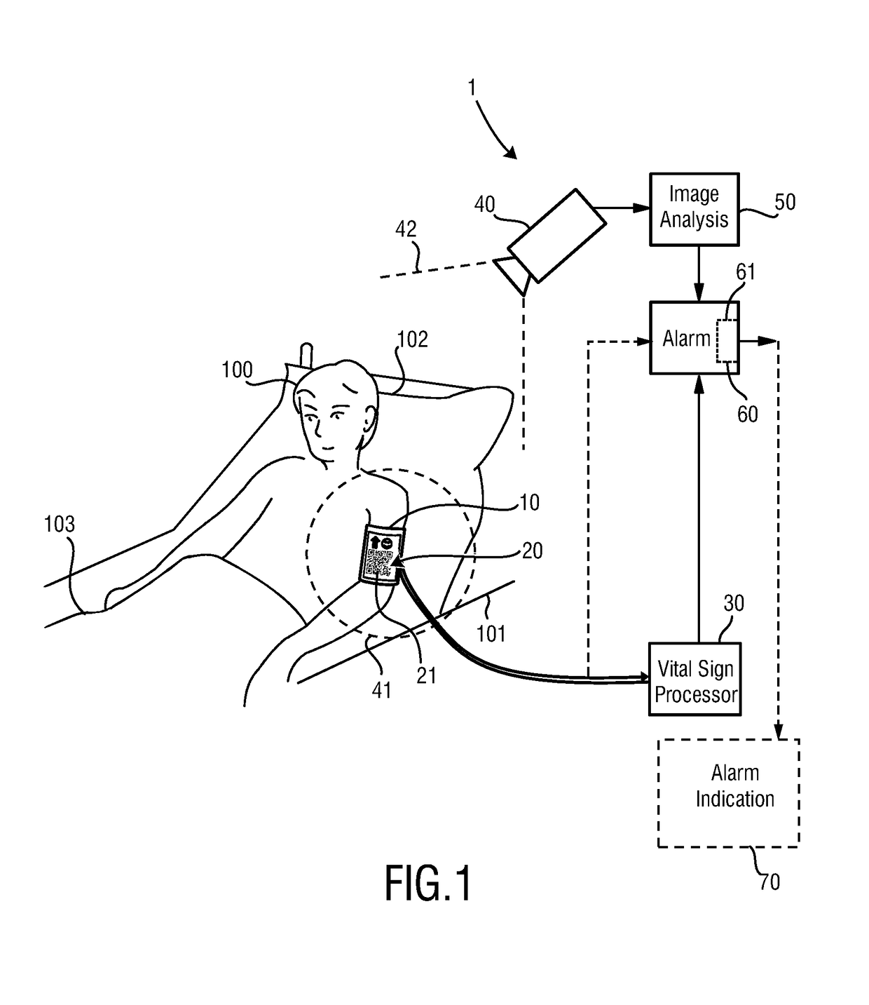
[0049]FIG. 1 schematically shows a system 1 for determining a vital sign of a subject 100. The subject 100, in this example a patient, lies in a bed 101, wherein the head of the subject 100 is located on a pillow 102 and the subject 100 is covered with a blanket 103. A sensor 10 is fixed to the subject 100 for measuring a vital sign information signal of said subject. Here, the sensor 10 is a blood pressure cuff arranged on the subject's upper are for measuring the blood pressure of the subject 100.

[0050]A marker 20 is attached to the sensor 10, e.g. printed on the outer surface of the blood pressure cuff or attached there in the form of a sticker. In this embodiment the marker 20 is a passive marker comprising a graphical pattern 21, here a so-called QR-code. The QR-code may feature different structural elements allowing for a machine-readable determination of the orientation and / or location of the graphical pattern 21. The marker 20 may be visible or invisible to the human eye, e....

second embodiment

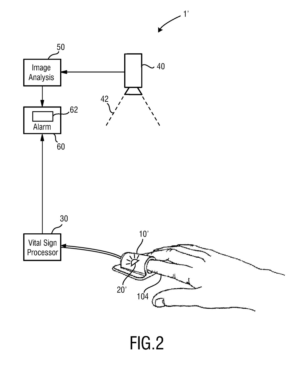
[0063]FIG. 2 schematically shows a system 1′ for determining a vital sign of a subject 100. In this embodiment a pulse oximeter in the form of a fingerclip is used as sensor 10′, which is arranged at a patient's finger 104 for continuously measuring the oxygen saturation (SpO2) as vital sign. Such pulse oximeters are generally known in the art and shall not be described herein in more detail.

[0064]In or on the sensor 10′ an active marker 20′ is arranged, here in form of a light source, e.g. an LED emitting visible or infrared light. Within the image data the imaging unit 40 can detect the active marker 20′ and can detect movements of the active marker 20′ (and, thus, of the sensor 10′) over time. The other elements of the system basically correspond to the corresponding elements of the system 1 shown in FIG. 1.

[0065]The marker 20′ can be thought of as a light beacon, which emits light into the environment. The intensity of the light can be time varying, i.e., coded light can be emit...

third embodiment

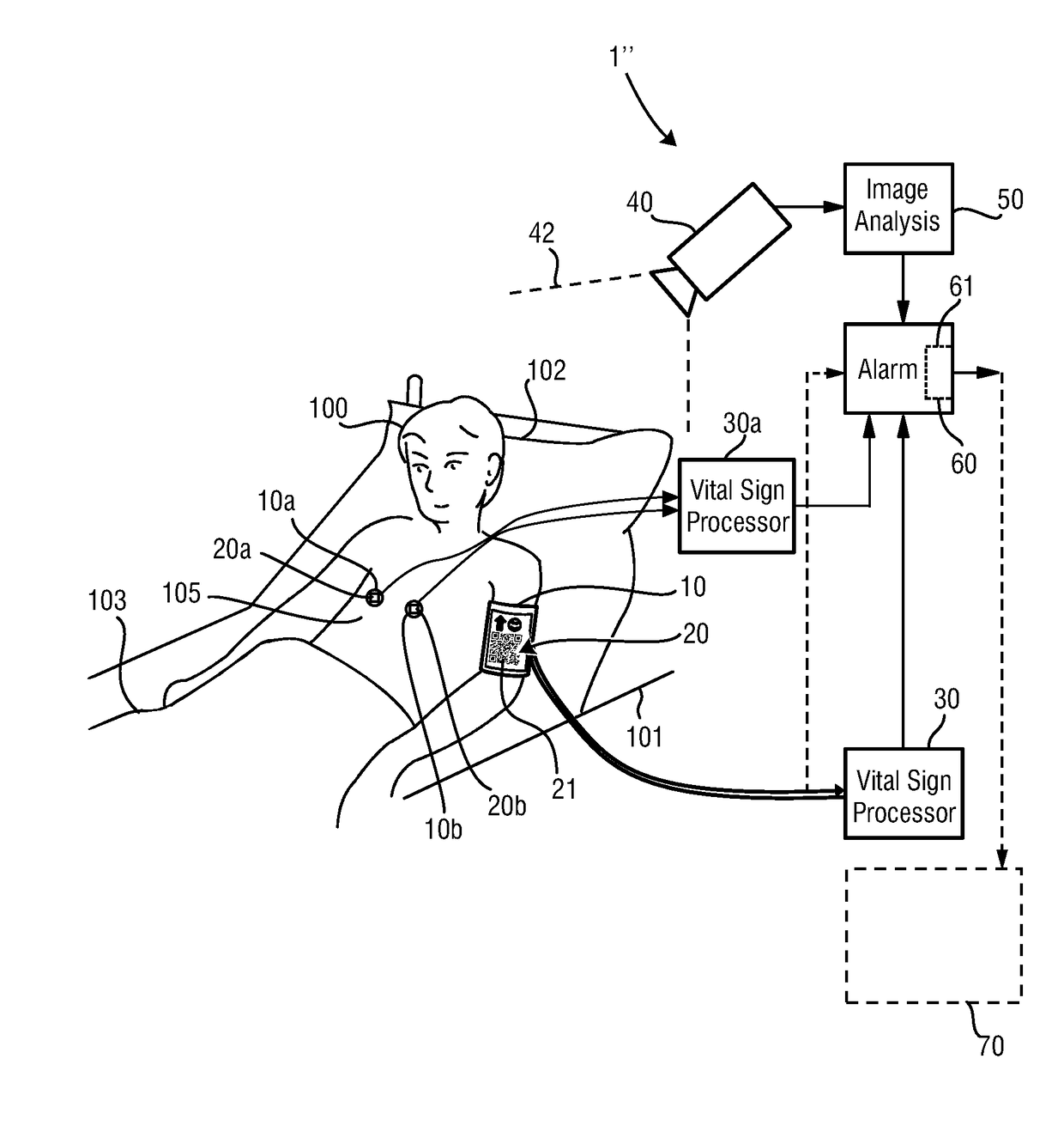
[0078]FIG. 3 schematically shows a system 1″ for determining a vital sign of a subject 100. In this embodiment the system 1″ comprises, in addition to the elements of the system 1 shown in FIG. 1, additional sensors 10a, 10b which are ECG electrodes attached to the chest 105 of the subject 100 for measuring an ECG signal. The electrode signals are provided to an additional vital sign processor 30a (or, alternatively, to the vital sign processor 30) where the electrode signals are evaluated to obtain the ECG signal as additional vital sign which is also provided to the alarm unit 60.

[0079]Each of said additional sensors 10a, 10b is provided with a respective marker 20a, 20b, which may be active or passive markers as described above. The markers 21a, 21b are also monitored by the imaging unit 40 to detect their motion and, thus, motion of the sensors 10a, 10b. Thus, for each individual sensor 10, 10a, 10b it can be judged how reliable the signal measured by the respective sensor is. F...


PUM


Abstract

A system for determining a vital sign of a subject releases the likelihood of generating and outputting false alarms. The system includes a vital sign processor that processes the vital sign information signal measured by a sensor attached to a subject to obtain a vital sign of said subject. An image analysis unit detects motion of a marker attached to the sensor from image data obtained by an imaging unit from at least an imaging region containing the sensor. An alarm unit generates and outputs an alarm signal based (1) on the measured vital sign information signal and / or the obtained vital sign and (2) the detected motion of said marker.

Description

CROSS REFERENCE TO RELATED APPLICATIONS[0001]This application claims the benefit of U.S. provisional application Ser. No. 61 / 765,096 filed Feb. 15, 2013 and European provisional application serial no. 13155430.5 filed Feb. 15, 2013, both of which are incorporated herein by reference.FIELD OF THE INVENTION[0002]The present invention relates a system and method for determining a vital sign of a subject and to a sensor for use in such a system and method. The present invention particularly relates to patient monitoring systems and methods, e.g. as used in intensive care units in hospitals.BACKGROUND OF THE INVENTION[0003]Vital signs of a person, for example heart rate (HR), respiration rate (RR) or oxygen saturation (i.e. SpO2), serve as indicators of the current state of a subject (i.e. a person or animal) and as powerful predictors of serious medical events. For this reason, vital signs are monitored in inpatient and outpatient care settings, at home or in further health, leisure and...

Claims


Application Information

Patent Timeline
Patent Type & Authority Patents(United States)
IPC IPC(8): A61B5/1455A61B5/024A61B5/00A61B5/11
CPCA61B5/14551A61B5/0002A61B5/746A61B5/1127A61B5/7221A61B5/02416
Inventor BRESCH, ERIKMUEHLSTEFF, JENS
Owner KONINKLJIJKE PHILIPS NV
Learn More