
Radiative cooling structures and systems

a cooling structure and radiation technology, applied in the field of radiation cooling structures and systems, can solve the problems of large power density mismatch between, and achieve the effects of convenient production and integration, low cost, and improved efficiency

Active Publication Date: 2019-03-21
UNIV OF COLORADO THE REGENTS OF +1
View PDF1 Cites 24 Cited by
  • Summary
  • Abstract
  • Description
  • Claims
  • Application Information

AI Technical Summary

Benefits of technology

The patent text is about polymer-based structures that can be used for selective radiative cooling, meaning they can be used to remove heat from a body by using specific wavelengths of light. These structures are made from a polymer or a polymer matrix composite material, and can be in the form of a sheet, film, or coating. They can be used during the day or night and are a lower cost, more effective, and easier to manufacture and integrate than inorganic optical coatings. The selective radiative cooling structures described in the text have been designed to absorb less solar energy and maximize infrared radiation in one or more atmospheric transmission windows, making them more efficient at cooling.

Problems solved by technology

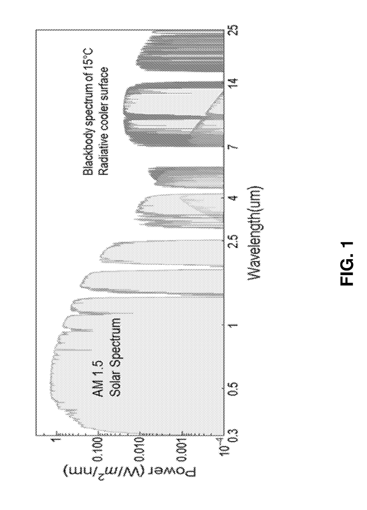
There is a large power density mismatch between the two spectra with relatively large heating power coming from the solar spectrum versus the potential self-cooling by thermal radiation through the atmospheric transmission window.

Method used


Image

  • Radiative cooling structures and systems
  • Radiative cooling structures and systems
  • Radiative cooling structures and systems

Examples


example 1

Polymethylpentene-Based Radiative Cooling Films

[0125]FIG. 13A shows the emissivity / absorptivity as a function of electromagnetic wavelength for a 50-μm-thick bare polymethylpentene (TPX™) films and a 50 μm thick film with 5% 8-μm-diameter solid silica microspheres. The trace for the TPX™ film is lighter gray than the trace for the composite film. Polymethylpentene is index-matched with silica in the solar spectrum, but not in the infrared spectrum. The polymethylpentene film mixed with silica microspheres results in a high emissivity at IR wavelengths of 7-13 μm. Without wishing to be bound by any particular belief, the silica spheres are believed to act as infrared scatterers and resonantly interact with infrared radiation, contributing to improved infrared emissivity of the films.

[0126]FIG. 13B shows the emissivity / absorptivity as a function of wavelength for polymethylpentene films of different thickness with 5% volumetric fraction of 8-μm-diameter solid silica microspheres. (key...

example 2

Scalable-Manufactured Randomized Glass-Polymer Hybrid Metamaterial for Day-time Radiative Cooling

[0129]Passive radiative cooling draws heat from surfaces and radiates it into space as infrared radiation to which the atmosphere is transparent. However, the energy density mismatch between solar irradiance and the low infrared radiation flux from a near-ambient-temperature surface require materials that strongly emit thermal energy and barely absorb sunlight. We embedded resonant polar dielectric microspheres randomly in a polymeric matrix, resulting in a metamaterial that is fully transparent to the solar spectrum while having an infrared emissivity greater than 0.93 across the atmospheric window. When backed with silver coating, the metamaterial shows a noon-time radiative cooling power of 93 W / m2 under direct sunshine. More critically, we demonstrated high-throughput, economical roll-to-roll manufacturing of the metamaterial, vital for promoting radiative cooling as a viable energy ...


PUM

PropertyMeasurementUnit
Temperatureaaaaaaaaaa
Lengthaaaaaaaaaa
Lengthaaaaaaaaaa

Abstract

Polymer-based selective radiative cooling structures are provided which include a selectively emissive layer of a polymer or a polymer matrix composite material. Exemplary selective radiative cooling structures are in the form of a sheet, film or coating. Also provided are methods for removing heat from a body by selective thermal radiation using polymer-based selective radiative cooling structures.

Description

CROSS-REFERENCE TO RELATED APPLICATIONS[0001]This application claims the benefit of U.S. Provisional Patent Application No. 62 / 456,540 filed Feb. 8, 2017 and U.S. application Ser. No. 15 / 056,680 filed Feb. 29, 2016, each of which is hereby incorporated by reference to the extent not inconsistent herewith.STATEMENT REGARDING FEDERALLY SPONSORED RESEARCH OR DEVELOPMENT[0002]This invention was made with government support under grant number DE-AR0000580 awarded by the Department of Energy's Advanced Research Projects Agency-Energy (ARPA-E). The government has certain rights in the invention.BACKGROUND OF THE INVENTION[0003]Radiative cooling features the release of heat from an object or surface in the form of thermal radiation, thereby lowering the temperature of the object or surface, or maintaining its temperature at a relatively lower baseline when operating in steady state. The thermal radiation emitted from a non-zero-temperature surface (in Kelvin) has a continuous wavelength or ...

Claims


Application Information

Patent Timeline
IPC IPC(8): F28F13/18F25B23/00B32B17/10
CPCF28F13/18F25B23/003B32B17/10238C08K3/36F28F2245/06F28B9/06B29C70/58B29C48/08B29C70/882B29C48/9135B29C48/022B29K2995/0006B29C70/88H01L31/048H01L31/02167H01L31/052Y02A40/966Y02E10/50C08K3/01C08K2201/005F24F5/0092F28D20/00Y02E60/14
Inventor YANG, RONGGUIYIN, XIAOBOTAN, GANGZHAO, DONGLIANGMA, YAOGUANGZHAI, YAO
Owner UNIV OF COLORADO THE REGENTS OF
Learn More