Hybrid Power Supply Unit For Audio Amplifier

a hybrid power supply and audio amplifier technology, applied in the direction of transportation and packaging, low frequency amplifiers, and battery arrangements for several simultaneous batteries, can solve the problems of low power supply average power level, high energy consumption, and high energy consumption, and achieve the effect of improving discharge characteristics, reducing physical size of audio amplifiers, and improving discharge characteristics

Inactive Publication Date: 2019-02-28
ZIMNICKI CHARLES +1
View PDF5 Cites 5 Cited by
  • Summary
  • Abstract
  • Description
  • Claims
  • Application Information

AI Technical Summary

Benefits of technology

[0044]A further advantage of the present disclosure is to provide a hybrid power audio supply with improved discharge characteristics over prior approaches, because modern rechargeable batteries typically have flat discharge curves rather than the exponential decay of a capacitor.
[0045]A further advantage of the present disclosure is to provide a hybrid power audio supply with improved discharge characteristics over prior approaches.
[0046]Still a further advantage of the present disclosure is a reduction of the physical size of the audio amplifier because of the high energy density of the battery stack of the power supply unit.
[0047]Yet another advantage of the present disclosure is further reduction in size in the power supply unit because the main power supply is scaled to audio power averaged over seconds / minutes as opposed to milliseconds as with the present art.
[0048]Another advantage of the present disclosure is improved audio performance due to decreased audio noise—resulting from the reduction of the capacity of the main power supply. Assuming a switching power supply, the electromagnetic noise (unintentionally) produced is substantially proportional to the size and power of the unit.
[0049]Yet another advantage of the present disclosure is providing increased power efficiency because the main power supply “sees” a constant load. Batteries perform the job of load averaging over a substantial time, so the load appears nearly constant to the power supply. In other words, the batteries equalize power demand so now the power supply can be scaled down to its most efficient operational range.

Problems solved by technology

Generally, a longer time constant energy storage mechanism would result in “better” (or more efficient) averaging, resulting in lower average power level required of the power supply.
Because instantaneous and (very short-time-scale) average power demands of audio are orders of magnitude greater than the average power consumed over long timescales (say greater than one second); power supplies of the existing art are poorly suited for the tasks of:providing a wide range of on-demand powerkeeping the efficiency highbeing able to realize both of the above at relatively low cost and small size
A first known approach to satisfying the peak demands of an audio amplifier will be called the “brute force solution,” which can be effective but it is costly, very inefficient, very large and heavy.
P=22 A*80V=1760 W. Furthermore, there is an energy loss penalty to be paid.
Even if the power supply was 90% efficient, the loss would translate to roughly 176 W of power, which would be comparable to the 250 W power output of the amplifier (which in turn would make the total solution very inefficient).
Such solution would definitely not be considered environmentally friendly.
In addition, such an over-sized power supply would be much larger and heavier physically, making a solution unattractive (both from a cost and aesthetics point of view).
Finally, the cost of “oversizing” the power supply by almost 10× makes it a poor solution for a product produced by for a profit-driven company and customers that wish to be responsible consumers of energy.
Through some basic calculations, we can see that it would be difficult and costly to provide a capacitor bank sufficient for storing energy over a substantial amount of time.
Nevertheless, such solutions are still physically large and costly.
It would be impractical to build decoupling networks to provide storage times longer than 50 mS, no matter how desirable—simply because of the physical volume of such a scaled solution would be even larger.

Method used


Image

  • Hybrid Power Supply Unit For Audio Amplifier
  • Hybrid Power Supply Unit For Audio Amplifier
  • Hybrid Power Supply Unit For Audio Amplifier

Examples


Embodiment Construction

[0077]Set forth below is a description of what is currently believed to be the preferred embodiment or best examples of the invention claimed. Future and present alternatives and modifications to this preferred embodiment are contemplated. Any alternatives or modifications which make insubstantial changes in function, in purpose, in structure or in result are intended to be covered by the claims in this patent.

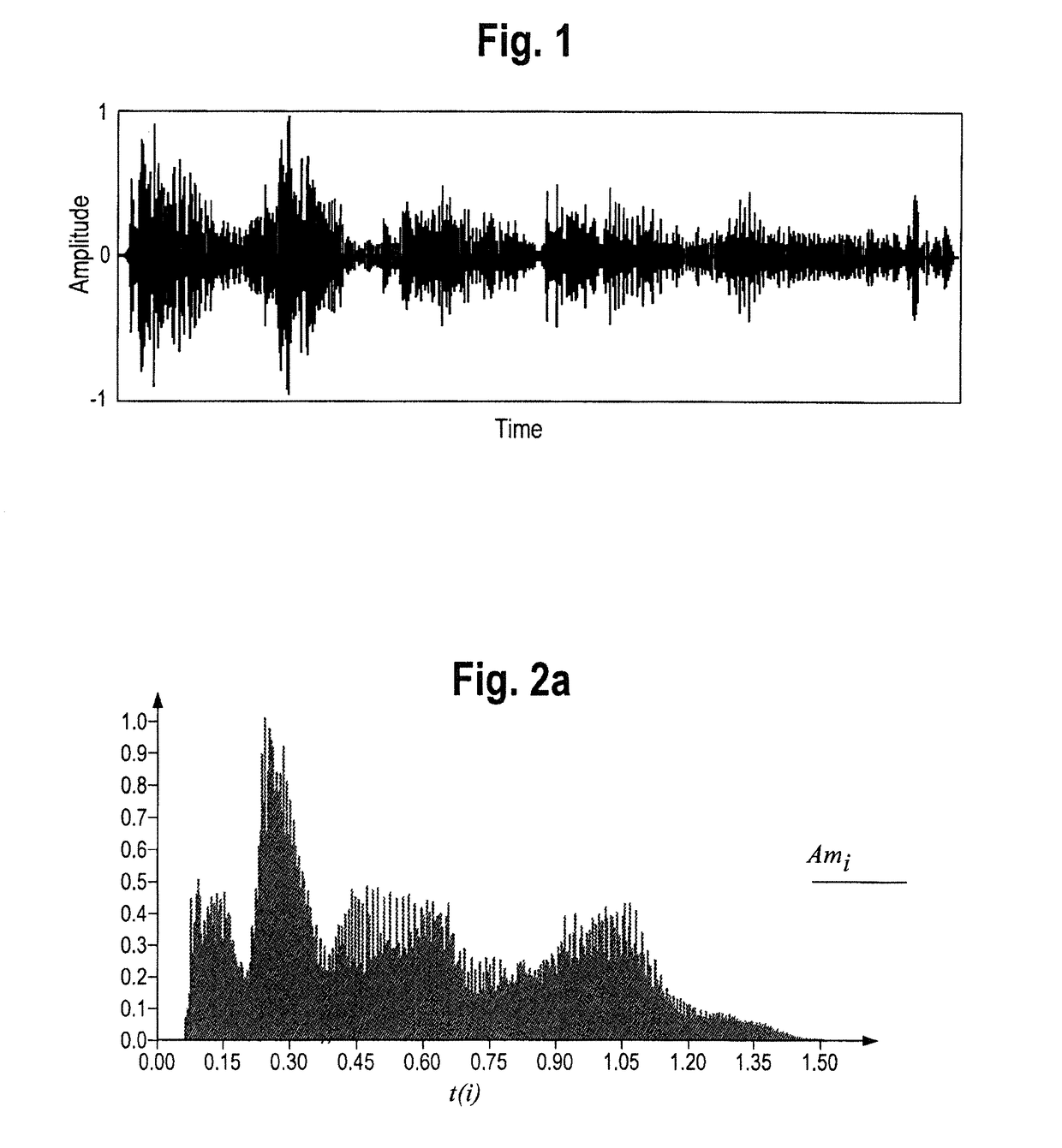
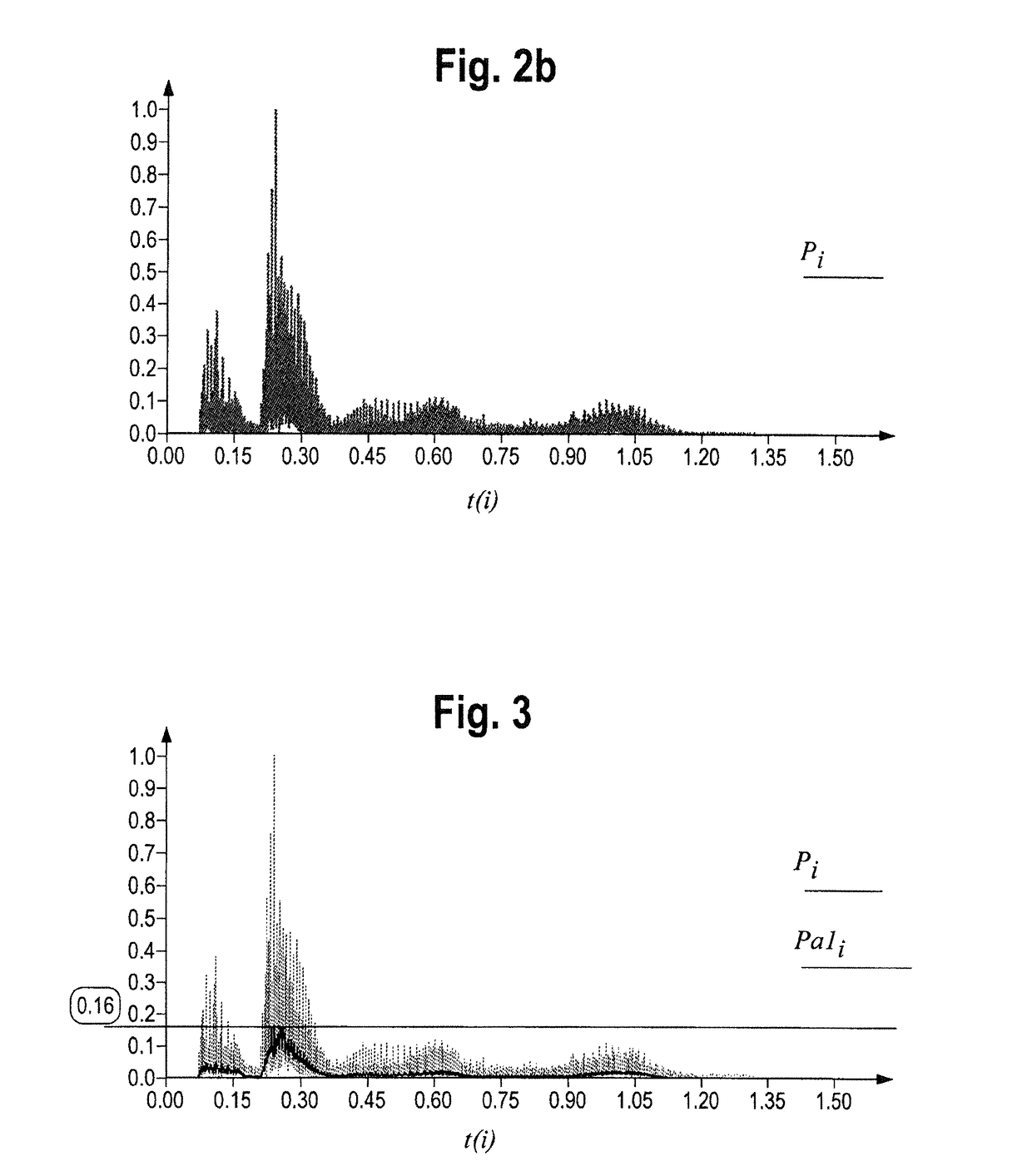
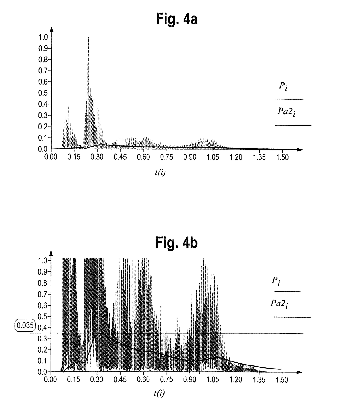
[0078]As seen in FIG. 1-5, the present disclosure involves a method and system for providing a hybrid power supply unit (i.e., a Mains-based, plug-in power supply continually replenishing an electrochemical decoupling network to an audio amplifier system. This process, as shown in FIG. 1, involves supporting a music signal, which appears as a complex, aperiodic and continuously varying AC waveform. As shown in FIG. 2a, the relative voltage amplitude of even a short (1.5 second) music sample can vary wildly. Accordingly, as shown in FIG. 2b, the relative audio power requirement...


PUM


Abstract

A system and method for using a circuit for providing power from one or more battery packs charged by a AC-mains-provided electrical connection and which supply power to a hi-power, non-portable audio amplifier. The system includes a power supply sized to satisfy long time-basis average demands, a battery pack and with a controller which buffers or back-ends a power supply which is not otherwise capable of satisfying the variable load peak demands that an audio source imposes on the amplifier, while still maintaining a substantially constant battery charge over an extended period of time.

Description

RELATED APPLICATION DATA[0001]This application is a continuation in part of application Ser. No. 14 / 678,505, filed Apr. 3, 2015, which in claims priority to provisional patent application No. 61 / 975,249, filed on Apr. 4, 2014.FIELD OF THE DISCLOSURE[0002]The present disclosure relates to a system and method for the more efficient supply of power to an audio amplifier system. In particular, the present disclosure relates to the use of batteries on similar electrochemical energy storage units for instantaneously meeting peak power demands in an audio amplifier system.[0003]The present disclosure relates to a system and method for the more efficient supply of power to an audio amplifier system. In particular, the present disclosure relates to the use of batteries for equalizing power demands in a high-end / high-power, mains-connected audio amplifier system over a substantial time period (on the order of several seconds or minutes).BACKGROUND[0004]Traditionally, in an audio amplifier—ele...

Claims


Application Information

Patent Timeline
Patent Type & Authority Applications(United States)
IPC IPC(8): H02J7/00H03F3/185H03F3/21H02J7/02
CPCH02J7/0013H03F3/185H03F3/21H02J7/022H03F2200/03H03F3/217H02J7/0016H03F3/187
Inventor ZIMNICKI, CHARLESRACZYNSKI, WALTER
Owner ZIMNICKI CHARLES
Why Eureka
Try Eureka