
Phosphor and plasma display device

a technology of phosphor and display device, which is applied in the direction of discharge tube/lamp details, discharge tube luminescnet screens, gas-filled discharge tubes, etc., can solve the problems of deterioration in brightness, increase in surface area of phosphors, and increase of defects on the surface of phosphors, so as to improve discharge characteristics, improve brightness, and improve the effect of phosphor brightness

Inactive Publication Date: 2005-03-24
PANASONIC CORP
View PDF5 Cites 36 Cited by
  • Summary
  • Abstract
  • Description
  • Claims
  • Application Information

AI Technical Summary

Benefits of technology

"The present invention provides a phosphor and a plasma display device that have improved discharge characteristics and reduced deterioration in brightness and chromaticity. The phosphor has a higher concentration of M near the surface of the particles, which enhances its performance. The plasma display device includes a plasma display panel and phosphor layers that are excited by ultraviolet rays to emit light. The blue phosphor is an alkaline-earth metal aluminate phosphor containing an element M, which has a higher concentration of M near the surface of the particles. This improves the performance of the plasma display device."

Problems solved by technology

However, when the particle diameters of the phosphor particles are decreased, the surface area of the phosphors would increase or defects on the surface of the phosphors would increase.
Therefore, a large amount of the water is ejected in a panel during the course of a panel manufacturing process, and problems occur, such as deterioration in brightness caused by the reaction with the phosphor and MgO during the discharge (particularly, deterioration in brightness of blue and green), a change in chromaticity of the panel (shift in color caused by the change in chromaticity and burn-in of a screen), a decrease in driving margin and an increase in discharge voltage.
Furthermore, when vacuum ultraviolet light (VUV) of 147 nm is adsorbed to the oxygen defects, another problem occurs such that the defects further increase, which further increases deterioration in brightness of the phosphor.
However, the coating on the entire surface causes the absorption of ultraviolet rays, which results in a problem of a decrease in brightness of light emitted from the phosphors and a problem of a decrease in brightness due to ultraviolet rays.

Method used


Image

  • Phosphor and plasma display device
  • Phosphor and plasma display device
  • Phosphor and plasma display device

Examples


experiment 1

[0115] (Experiment 1)

[0116] As for the thus manufactured samples 1 to 10 and the comparative sample 11, the brightness for the respective colors after the phosphor baking step (520° C., 20 min.) in the rear panel manufacturing process was measured. Then, after the panel bonding step (sealing step at 450° C. for 20 min.) in the panel manufacturing process, the rates of change (deterioration) in the brightness for the respective phosphors were measured.

experiment 2

[0117] (Experiment 2)

[0118] The brightness of the illumination states of a panel for the respective colors and the rates of change (deterioration) in the brightness were measured as follows: discharge sustaining pulses with a voltage of 180 V and a frequency of 100 kHz were applied to a plasma display device continuously for 1000 hours life test) and the panel brightness before and after the test was measured. From the measurement results, the rate of change (deterioration) in brightness ([{brightness after the test—brightness before the test} / brightness before the test]×100) was determined. Address errors during the address discharge were judged from the observation of an image so as to check flickering. When flickering occurred even at one point, this was judged as an error. Furthermore, the brightness distribution, uneven color and shift in color of the panel were determined by measuring the brightness of a white image by a luminance meter and were judged from the overall distrib...

experiment 3

[0120] (Experiment 3)

[0121] The phosphors in all colors were recovered from samples 1 to 10 and comparative sample 11, and the amounts of the absorbed gas of these phosphors were measured using a TDS analyzer (thermal desorption spectrometry apparatus), where outgassing amounts of water, CO2 and hydrocarbon gas at 100° C. to 600° C. were measured. Next, assuming that the total outgassing amount of water, CO2 and hydrocarbon gas (mass number 40 or more) of sample 1 was 1, the relative amounts of samples 2 to 10 and the comparative sample 11 were measured so as to measure the relative values of the gas amounts contained in the phosphors. Table 4 shows these results also.

TABLE 4Unevencolor andPresenceshift inBrightness ofRate ofofcolorphosphorschangeaddressduringRate ofinerrorsilluminationdeterioration1)brightness2)duringstate ofRelativeSample(%)(%)addresswhite fullratio ofNo.BlueRedGreenBlueRedGreendischargedisplayadsorbate3)1−0.8−1.2−3.0−0.7−1.0−2.8NoNo12−0.5−1.2−3.1−0.5−0.9−2.5NoN...


PUM

PropertyMeasurementUnit
particle diameteraaaaaaaaaa
temperaturesaaaaaaaaaa

Abstract

Phosphor and a plasma display device are provided whose deterioration in brightness of phosphors and a degree of change in chromaticity are alleviated and whose discharge characteristics are improved and that has excellent initial characteristics. Phosphor of the present invention is an alkaline-earth metal aluminate phosphor containing an element M (where M denotes at least one type of element selected from the group consisting of Nb, Ta, W and B). In this phosphor, a concentration of M in the vicinity of a surface of the phosphor particles is higher than the average concentration of M in the phosphor particles as a whole. A plasma display device according to the present invention includes a plasma display panel in which a plurality of discharge cells in one color or in a plurality of colors are arranged and phosphor layers are arranged so as to correspond to the discharge cells in colors and in which light is emitted by exciting the phosphor layers with ultraviolet rays. The phosphor layers include blue phosphor, where the afore-mentioned phosphor is used as the blue phosphor.

Description

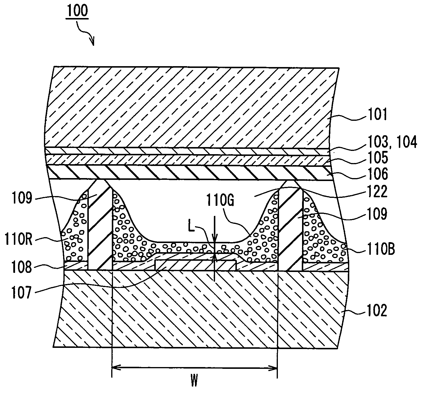
FIELD OF THE INVENTION [0001] The present invention relates to phosphor used for a plasma display panel and a mercury-free discharge lamp and relates to a plasma display device. BACKGROUND OF THE INVENTION [0002] In recent years, in the field of color display devices used for computers and TVs to display images, a display device employing a plasma display panel (hereinafter also referred to as PDP) has received attention because such a device enables a large size, low profile and light-weight color display device. A plasma display device utilizing a PDP performs full color displaying by conducting additive color mixture of so-called three primary colors (red, green and blue). In order to perform such full color displaying, a plasma display device is provided with phosphor layers that emit light in respective colors including red (R), green (G) and blue (B) as the three primary colors, and phosphor particles making up these phosphor layers are excited by ultraviolet rays generated in...

Claims


Application Information

Patent Timeline
Patent Type & Authority Applications(United States)
IPC IPC(8): C09K11/08C09K11/55C09K11/59C09K11/64C09K11/67C09K11/68C09K11/77C09K11/80H01J1/62H01J1/63H01J11/00H01J11/22H01J11/24H01J11/34H01J11/42H01J63/04
CPCC09K11/595C09K11/7734H01J2211/42H01J1/63C09K11/778C09K11/55
Inventor OKUYAMA, KOJIROZUKAWA, TAKEHIROSAKAI, MASAHIROSHIRAISHI, SEIGOSUGIMOTO, KAZUHIKOAOKI, MASAKIHIBINO, JUNICHI
Owner PANASONIC CORP
Learn More